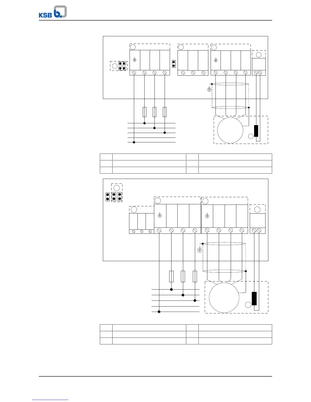
Fig.24: Establishing the power supply and motor connections, size D
① Mains connection ② Motor connection
③ PTC connection ④ Braking resistor
⑤ Motor PTC ⑥ Jumper for IT mains
Size E
Fig.25: Establishing the power supply and motor connections, size E
① Mains connection ② Motor connection
③ PTC connection ④ Braking resistor
⑤ Motor PTC ⑥ Jumper for IT mains
Connecting motor
monitoring devices (PTC/
PTC thermistor)
Connect the cores for a PTC connection/PTC thermistor to the PTC terminal strip (3). If
no PTC connection is available on the motor side, parameter 3-2-3-1 (PTC Analysis)
must be deactivated.