7 Installation at Site
45 of 212
PumpDrive 2
DANGER
Opening the protective cover with the master switch in the OFF position
Risk of fatal injury due to electric shock!
▷ Disconnect the frequency inverter from the mains before carrying out any
maintenance and installation work.
▷ Prevent the frequency inverter from being re-started unintentionally when
carrying out any maintenance and installation work.
ü The master switch has been installed in the protective cover.
1. Guide the power cable through the cable gland.
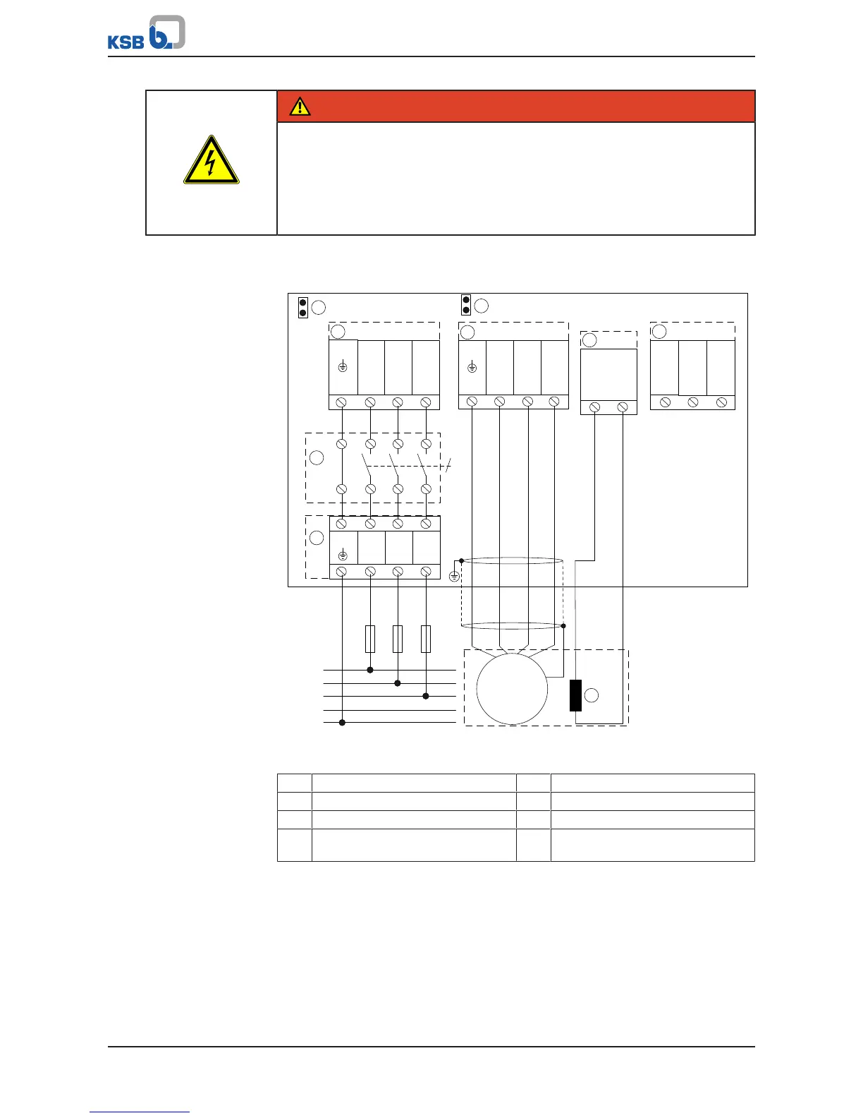
Fig.26: Example of power supply connection and motor connection to designated
terminals, size B
① Mains connection ② Motor connection
③ PTC connection ④ Braking resistor
⑤ Motor PTC ⑥ Jumper for IT mains
⑦ Power supply connection terminal
for master switch version
⑧ Master switch
2. Sizes A, B and C: Connect the power cable and the motor connection cable to
the designated terminals on the inside of the protective cover.
Sizes D and E: Connect the power cable and motor connection cable directly to
the master switch.