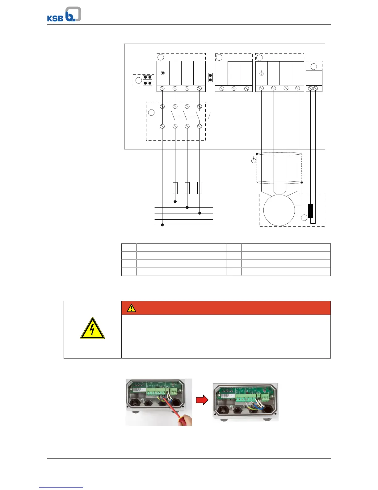
Fig.27: Example of power supply connection and motor connection to designated
terminals, size D
① Mains connection ② Motor connection
③ PTC connection ④ Braking resistor
⑤ Motor PTC ⑥ Jumper for IT mains
⑧ Master switch
7.4.3.3.2 Directly connect motor cable without motor connector (for sizes A and B
only)
DANGER
Improper electrical connection
Risk of fatal injury due to electric shock!
▷ Never simultaneously use the motor connector with a motor cable that is
directly connected to the motor terminals.
▷ Never touch terminals and connectors of the motor connector.
When directly connecting a motor line to the designated motor terminals (U, V, W),
the motor connector fitted at the factory must first be removed.
Fig.28: Disconnecting the cores of the motor connector
1. Disconnect the cores of the motor connector at terminals U, V and W.