About Typical VFD Motor Drive Control
6-13
KVAL 994-X Operation/Service Manual
About the VFD
A VFD (Variable Frequency Drive) takes the raw input from the 3 phase line voltage and converts
it by varying the frequency and voltage of the input voltage. Changes in the output voltage varies
speed and force of the motor. For example: A lower frequency will result in a slower speed.
The VFD converts the voltage but is “told what to do” by the PLC (Programical Logic Control-
ler). The output voltage is then sent to the motor. For a block diagram, see Figure 6- 29 on page 6-
12
.
VFD models vary in KVAL machines depending on where it is used, voltage requirements and
type of PLC used. This is a general view on the VFD. See the machine’s Electrical Print for
detailed information.
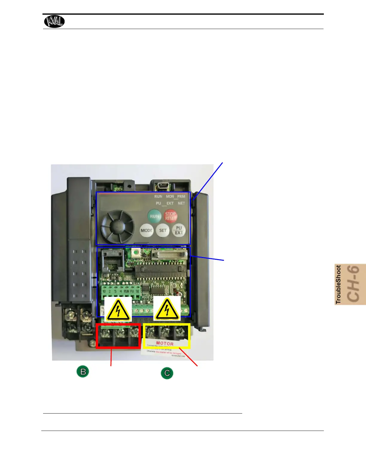
Line Voltage IN
Converted Signal OUT to Motor
Operation Panel: Access to
manual operation VFD. This
panel can be used for trouble-
shooting purposes. Fault
Errors will be displayed if any
occur.
During normal operation the
Run LED is lit or flickers and
the frequency of the motor is
displayed.
Control Circuit Board: Con-
tains connections to PLC and
other control circuits.
Includes:
• Control input signals
• Speed Functions
• Relay Outputs
• Jumpers
• Output to reset switch
FIGURE 6- 30. Sample of VFD