About a Typical Pneumatic Circuit
6-17
KVAL 994-X Operation/Service Manual
About Cylinder Operation
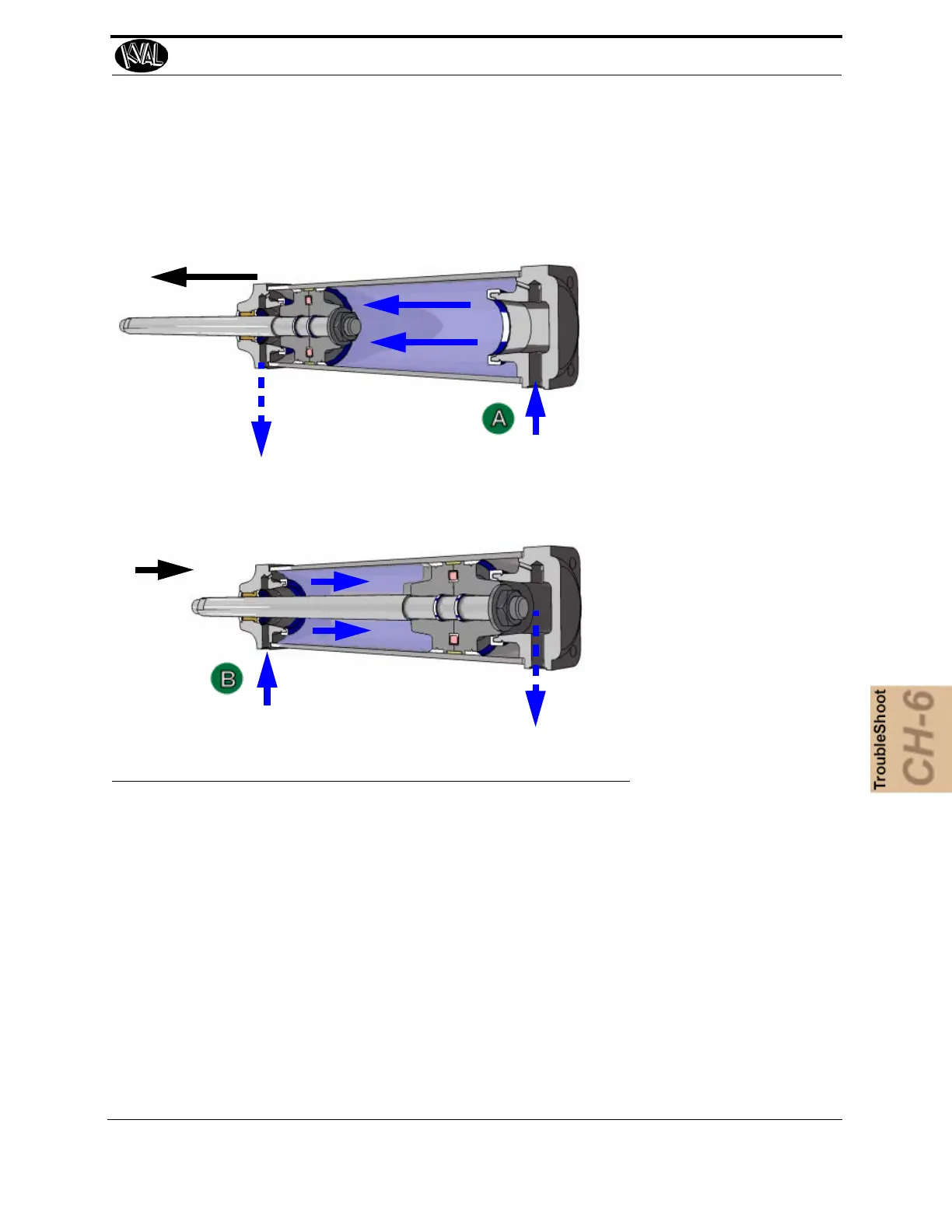
To see a block diagram of general pneumatic connections, see Figure 6- 32 on page 6-15. The fig-
ure below, shows a cross-section of a cylinder in action.
Retract Motion
Extend Motion
Air
Air
1. PLC drives Control Valve.
2. Valve delivers compressed
air to the cylinder.
3. Cylinder piston rod is
extended when air is
delivered to port “A”
4.
Cylinder piston rod is
retracted when air is
delivered to port “B”
FIGURE 6- 35. Cross-section of Air Cylinder
How the Pneumatic System Works
The Pneumatic system consists of a brain (PLC), an action (Positioning System), and a result
(Moving the Load). For a generalized representative, this section describes the process to
move a router to the extend and the retract position with a double valve.
Extend Process
If PLC determines the conditions are right to extend the Router:
1. The PLC applies the control voltage to the Control Valve which directs com-
pressed air to extend port of the Cylinder.
2. The Cylinder and Router are extended deactivating the Retract Sensor
3.
The Router fully extends activating the Extend Sensor.