+100%
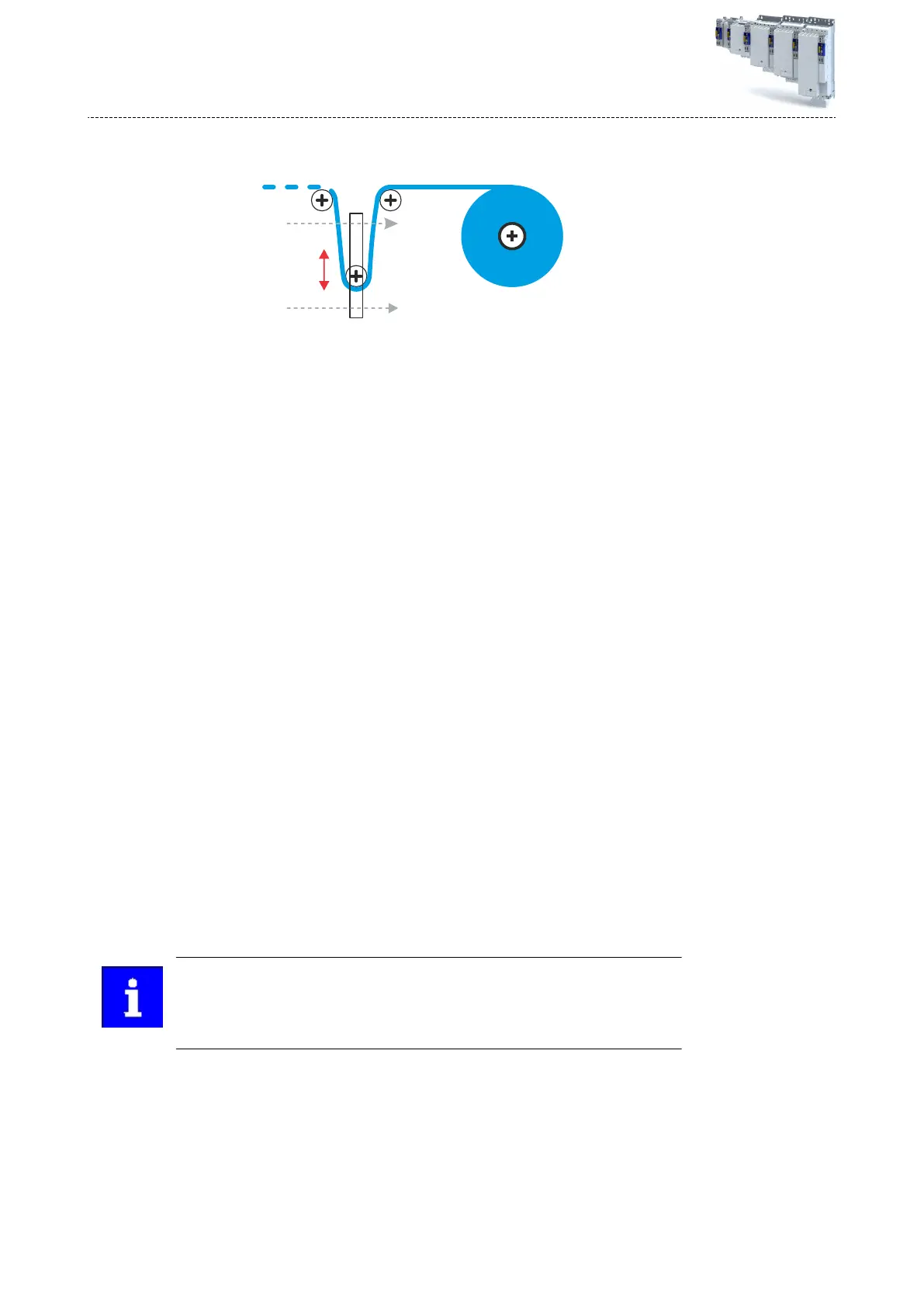
Dancer position
lower limit
-100%
Dancer position
upper limit
The maximum length of material is now saved in the dancer.
f
)
Set bit 30 in the parameter Control signals = FALSE/TRUE/FALSE. 40x5050:010 Bit 30
The reference value has now been taught.
g) Move the dancer manually to the upper posion.
The minimum length of material is now saved in the dancer.
h)
Se
t bit 25 in the parameter Control signals = FALSE/TRUE/FALSE. 40x5050:010 Bit 25
The reference value has now been taught.
i) In the parameter Eecve actual dancer posion, check the following:
The upper posion is shown as +100 [%] 40x5052:189
The lo
wer posion is shown as -100 [%] 40x5052:189
The middle posion is shown as 0 [%] 40x5052:189
6.
Check slave operaon at master value.
a) Start the speed-determining drive in the machine with a xed setpoint, e.g. +5 [%] in
the direcon in which the material moves to the rewinder.
b) In order for the third double word to transmit the line speed, the system bus must be
operaonal and the process data in the master have been congured accordingly.
c) Check whether the parameter Actual line velocity, is showing a value = 50.0000
[mm/s]. 40x5051:009
d) In the parameter Control signals, set bit 16 = TRUE and synchronise the winder with
the line speed. 40x5050:010
The ramps can be adapted via Acceleraon to synchronize to line velocity and Decel-
eraon to synchronize to line velocity.
Acceleraon to synchronize to line velocity 40x5051:020
Deceleraon to synchronize to line velocity 0x05051:021
e)
In the parameter Status signals, check whether the ramp phase is complete and
bit 16 = TRUE. 40x5050:110
Velocity actual value must show that the reel motor rotates at -150.8 [1/min] in an
non-inverted motor mount. 40x606C
7. Perform a controller adjustment.
At this point, there must not yet be any material in the machine and the dancer
mus
t be in the lower limit posion. If not, manually move the dancer into the
lower posion.
The diameter connues to be 76 [mm].
a) Set the double word 03 of the control interface "Dancer set Posion" to -90 [%].
b)
Set the double word 04 of the control interface "Dancer control inuence" to 10 [%].
c) In the parameter Control signals, set bit 18 = TRUE and enable the process controller.
40x5050:010 Bit 18
d) Check: The rewinder aempts to rewind material in order to pull the dancer from -100
[%] t
o the setpoint posion of -90 [%] via CCW rotaon of the winding sha.
The speed is the result of 10 [%] system deviaon mulplied by Gain = 1 and the inu-
ence of 10 [%] for approx. 30 [1/min] at d = 76 [mm].
Conguring the "Winder Dancer" TA
Commissioning
94

 Loading...


