Chapter 6 Basic Functions
6-8
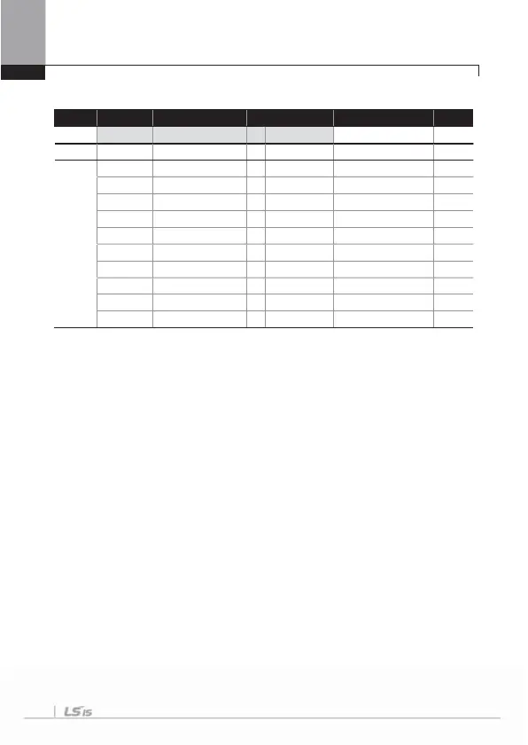
6) Frequency setting by Encoder Option Card (If you want use pulse input to
frequency command)
Group Code No. Function Display Setting Displayed Setting Frequency Unit
DRV 07 Freq Ref Src 7 Encoder
-
-
IN 01 Freq at 100% - 60.00
0.00~Max. Freq.
Hz
APO
01 Enc Opt Mode 2 Reference
0~2
-
04 Enc Type Sel 0 -
0~2
-
05 Enc Pulse Sel 2 A
0~2
-
06 Enc Pulse Num - -
10~4096
-
09 Pulse Monitor - -
-
kHz
10 Enc Filter - 10
0~10000
msec
11 Enc Pulse x1 - 0.0
0~100
kHz
12 Enc Perc Y1 - 0.00
0~100
%
13 Enc Pulse x2 - 100.0
0~100
kHz
14 Enc Perc y2 - 100.00
0~100
%
If you mount the encoder option card on the main body of the inverter, the code is
displayed from APO-01.
APO-01 Enc Opt Mode, APO-05 Enc Pulse Sel : Select No.2 Reference for APO-01
in order to set the frequency with the encoder. Set APO-05 at No.2 A.
APO-04 Enc Type Sel, APO-06 Enc Pulse Se l : inputs the output method and
number of pulses in harmony with the encoder specification.
APO-10 Enc Filter ~ APO-14 Enc Perc y2 : sets the filter time constant and minimum
and maximum input frequency of the encoder input. The output frequency
corresponding to the encoder input frequency is the same as that of voltage (V1) or
current (I1) input.
APO-09 Pulse Monitor: displays the frequency of the pulse which is input when APO-
01 Enc Opt Mode is set as Reference.

 Loading...


