Chapter 8 Table of Functions
G
8-20
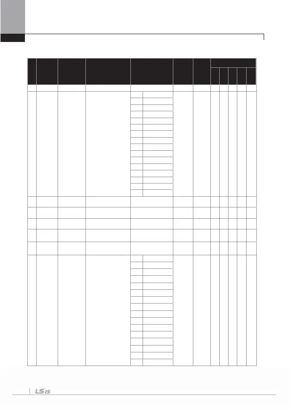
8.1.6 Parameter mode – Output terminal block function group (
OUT)
I
N
o.
Comm. No.
Function
Display
Name Setting Range
Initial
Value
Shift in
Operation
Control Mode
V/F
SL
VC
SLT
VCT
00
- Jum
Code
um
code
0~ 9
30
01
0h1601 AO1 Mode analog output1 item
0Fre
uenc
0:
Frequency
O O O O O O
1Curren
Volta
e
3 DC Link Vol
4Tor
ue
Wat
6Idse
7I
se
Ta r
et Fre
Ram
Fre
10 S
eed Fd
11 S
eed De
1
PIDRef Value
13 PIDFdb Value
14 PID Out
u
1
Constan
02
0h1602 AO1 Gain analog output1 gain -1000 ~ 1000 [%] 100.0
O O O O O O
03
0h1603 AO1 Bias analog output 1 bias -100 ~ 100 [%] 0.0
O O O O O O
04
0h1604 AO1 Filter analog output1 filter 0 ~ 10000 [ms] 5
O O O O O O
05
0h1605
O1
Const %
analog constant
output 1
0 ~ 100 [%] 0.0
O O O O O O
06
0h1606
O1
Monito
analog output 1
monito
0 ~ 1000 [%] 0.0
- O O O O O
07
0h1607 AO2 Mode analog output 2 item
0
Frequency
0:
Frequency
O O O O O O
1
Curren
2
Voltage
3
DC Link Vol
4
To r qu e
5
Wat
6
Idse
7
Iqse
8
Target Freq
9
Ramp Freq
10
Speed Fd
11
Speed De
12
PIDRef Value
13
PIDFd
Val ue
14
PID Outpu
1
Constan

 Loading...


