Chapter 8 Table of Functions
G
8-16
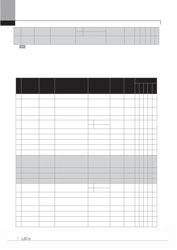
90 0h145A New AHR Sel
Selcting the Current anti-
hunting
0 N
0:No ż X X X X
1 Yes
91 0h145B AHR P-Gain
Current
nti-hunting
Function Protection
0~32767 1000 X ż X X X X
* The grey code refers to hidden code, emerging only in case of setting of the code.
Note 20)
CON-72~75 are displayed only when CON-71,77 (KEB Select) is set as “Yes”.
Note 21)
CON-82~83 are displayed only when DRV-09 (Control Mode) is set as “Vector”.
Note 22)
CON-78~79,86~89 are displayed only when CON-77 (KEB Select) is set as “Yes”.
8.1.5 Parameter mode – Input terminal block function group (
IN)
No. Comm. No.
Function
Display
Name Setting Range Initial Value
Shift in
Operation
Control Mode
V/
S
VC
SL
VCT
00
-
Jump Code jump code
0 ~ 99 65 O
ڪٻ ڪٻ ڪ ڪ ڪ
01
0h1501
Freq
at 100%
Analog maximum input frequency
Start freq. ~ max.
freq.[Hz]
60.00 O
ڪٻ ڪٻ ڪ ڳ ڳ
02
0h1502
To r qu e
at100%
Analog maximum input torque
0 ~ 200 [%] 100.0 O
ڳٻ ڳٻ ڪ ڪ ڪ
0
0h150
V1 Monitor
V] V1 input amount display
0
10 [V] 0.00 O
ڪٻ ڪٻ ڪ ڪ ڪ
06
0h1506
V1 Polarity V1 input polar selection
0 Unipola
0:
Unipolar
X
ڪٻ ڪٻ ڪ ڪ ڪ
1 Bipola
07
0h1507
V1 Filter V1 input filter time constant
0 ~ 10000 [ms] 10 O
ڪٻ ڪٻ ڪ ڪ ڪ
08
0h1508
V1 Volt x1 V1input minimum voltage
0 ~ 10 [V] 0.00 O
ڪٻ ڪٻ ڪ ڪ ڪ
09
0h1509
V1 Perc y1 V1minimum voltage output %
0 ~ 100 [%] 0.00 O
ڪٻ ڪٻ ڪ ڪ ڪ
10
0h150A
V1 Volt x2 V1input maximum voltage
0 ~ 10 [V] 10.00 O
ڪٻ ڪٻ ڪ ڪ ڪ
11
0h150B
V1 Perc y2 V1maximum voltage output %
0 ~ 100 [%] 100.00 O
ڪٻ ڪٻ ڪ ڪ ڪ
1
Note
22)
0h150C
V1 (–)Volt x1’ V1(–)input minimum voltage
-10 ~ 0 [V] 0.00 O
ڪٻ ڪٻ ڪ ڪ ڪ
13
0h150D
V1(–)Perc y1’ V1(–)minimum voltage output %
-100 ~ 0 [%] 0.00 O
ڪٻ ڪٻ ڪ ڪ ڪ
14
0h150E
V1(–)Volt x2’ V1(–)input maximum voltage
-10 ~ 0 [V] -10.00 O
ڪٻ ڪٻ ڪ ڪ ڪ
15
0h150F
V1(–)Perc y2’ V1(–)maximum voltage output %
-100 ~ 0 [%] -100.00 O
ڪٻ ڪٻ ڪ ڪ ڪ
16
0h1510
V1 Inverting rotation direction change
0N
0: No O
ڪٻ ڪٻ ڪ ڪ ڪ
1Ye
17
0h1511
V1 Quantizing V1 quantization level
0.04 ~ 10 [%] 0.04 X
ڪٻ ڪٻ ڪ ڪ ڪ
20
0h1514
I1
Monitor [mA]
I1input amount display
0 ~ 20 [mA] 0.00 O
ڪٻ ڪٻ ڪ ڪ ڪ
22
0h1516
I1 Filter I1input filter time constant
0 ~ 10000 [ms] 10 O
ڪٻ ڪٻ ڪ ڪ ڪ
23
0h1517
I1 Curr x1 I1input minimum current
0 ~ 20 [mA] 4.00 O
ڪٻ ڪٻ ڪ ڪ ڪ
24
0h1518
I1 Perc y1 Output at I1 minimum current %
0 ~ 100 [%] 0.00 O
ڪٻ ڪٻ ڪ ڪ ڪ
25
0h1519
I1 Curr x2 I1input maximum current
4 ~ 20 [mA] 20.00 O
ڪٻ ڪٻ ڪ ڪ ڪ

 Loading...


