Chapter 4 Wiring
4-22
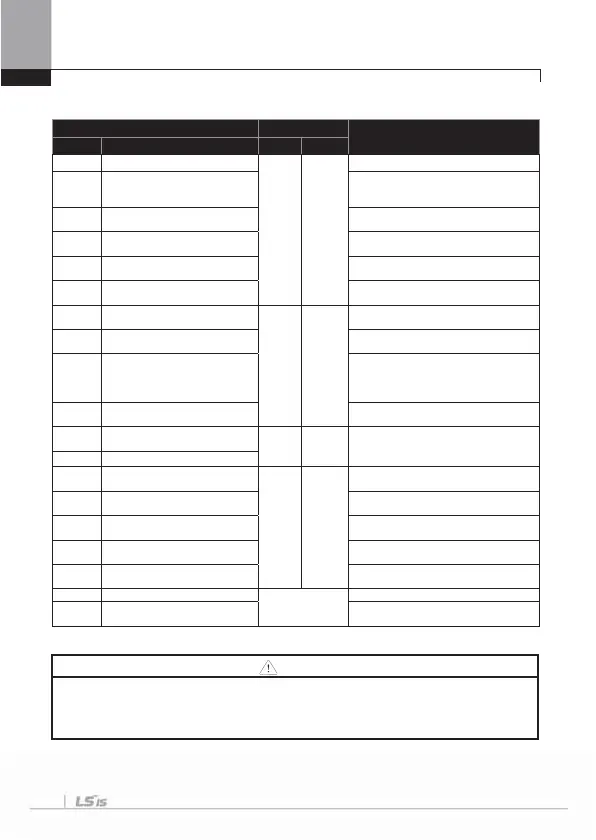
4.1.12 Specifications of signal terminal block distribution
Terminal Cable size
1)
Electric specifications
Type Name mm
AWG
P1~P8 Multi-function input terminal
0.33
~1.25
16~22
-
CM
Contact point common terminal
(In case of Basic I/O,
CM is different from 5G
Common earth for multi function input
terminal
VR+
nalog frequency setting
+
power suppl
Output voltage : +12V
Maximum output volta
e : 100m
VR-
nalog frequency setting
-
power suppl
Output voltage : -12V
Maximum output volta
e : 100m
V1
Multi-function analog voltage
input terminal
Input voltage : 0~10V or -10~10V
I1
Multi-function analog current input
terminal
0~20mA input
Internal resistance : 249ȍ
AO1
Multi-function analog voltage
output terminal
0.33
~2.0
14~22
Maximum output voltage : 10V
Maximum output current : 10m
AO2
Multi-function analog current
output terminal
Maximum output current : 20mA
5G
Frequency setting common
terminal
(In case of Basic I/O,
5G is different from CM
Common terminal of analog frequency
setting signal and analog current and
voltage terminals
Q1
Multi-function terminal
open collector
DC26V, below 100mA
EG
Earth terminal for external power
suppl
0.33
~1.25
16~22 Maximum output current : 150mA
24 External 24V power supply
A1
Multi function relay 1
output A contact point
0.33
~2.0
14~22
Below AC250V/5A, Below DC30V/5A
B1
Multi function relay 1
output B contact point
Below AC250V/5A, Below DC30V/5A
C1
Multi function relay 1
contact point common terminal
Below AC250V/5A, Below DC30V/5A
A2
Multi function relay 2
output A contact point
Below AC250V/5A, Below DC30V/5A
C2
Multi function relay 2
contact point common terminal
Below AC250V/5A, Below DC30V/5A
S+,S- RS485 signal input terminal
0.75mm
2
(18AWG)
RS485 signal line
CM RS485 common terminal
For multi connection, RS485 power
round
Shield
connection terminal
1) Apply the shielded type of twisted-pare wire.
Caution
Do not use more than 3M remote cable for the keypad. Failure of the signals on the keypad might
occur. To prevent radiated emissions in the analogical and digital signals, you must put a ferrite in
the wires of these signals.
Ex. Brand Würth Elektronik ref. 74271132

 Loading...


