Chapter 8 Table of Functions
G
8-1
8.1 Table of Functions
8.1.1 Parameter mode – DRV group(
DRV)
* The number of page is for User’s manual uploaded at LSIS website. You can
download the User’s manual which is described detailed function of parameter from
website. (http://www.lsis.biz
)
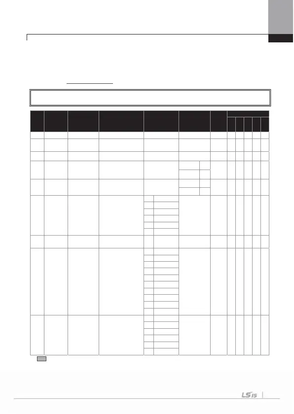
No. Comm. No.
Function
Display
Name Setting Range Initial Value
Shift in
Operation
Control Mod
V/F
SL
VC
SLT
VCT
00
- Jump Code
ump code
0~ 9
9
01
0h1101
Cmd
Fre
uenc
target frequency
0.0 ~ max. freq.[Hz]
0.0
O O O O X X
02
0h1102 Cmd Torque torque command
-180 ~ 180 [%]
0.0
O X X X O O
03
0h1103 Acc Time accelerating time
0 ~ 600 [s]
Below 75kW
20.0
O O O O O O
Above 90kW
60.0
04
0h1104 Dec Time decelerating time
0 ~ 600 [s]
Below 75kW
30.0
O O O O O O
bove 90kW
90.0
06
0h1106 Cmd Source
operating
command
method
0Ke
pad
1 : Fx/Rx-1
X O O O O O
1Fx/Rx-1
Fx/Rx-
3Int 48
4Field Bus
PL
07
0h1107 Freq Ref Src
frequency setting
method
0 Keypad-1
0 : Keypad-1
X O O O X X
08
0h1108 Trq Ref Src
torque command
method
0Ke
pad-1
0 : Keypad-1
X X X X O O
1Ke
pad-
V1
3I1
4V2
I
6Int 48
7 Encoder
Fied Bus
PL
09
Note1)
0h1109
Control
Mode
control mode
0V/F
0 : V/F
X O O O O O
1 V/F P
Slip Compe
3
Sensorles
1
4
Sensorles
2
Vector
* The grey code refers to hidden code, emerging only in case of setting of the code.
Note 1)
Effectiveness of each code according to the Control Mode setting
Refer to Option manual for options.
Control mode abbreviation: V/F: V/F (PG included), SL: Sensorles
-1, 2, VC: Vector,
SLT: Sensorless-1, 2 Torque, VCT: Vector Torque
G

 Loading...


