Chapter 4 Wiring
4-11
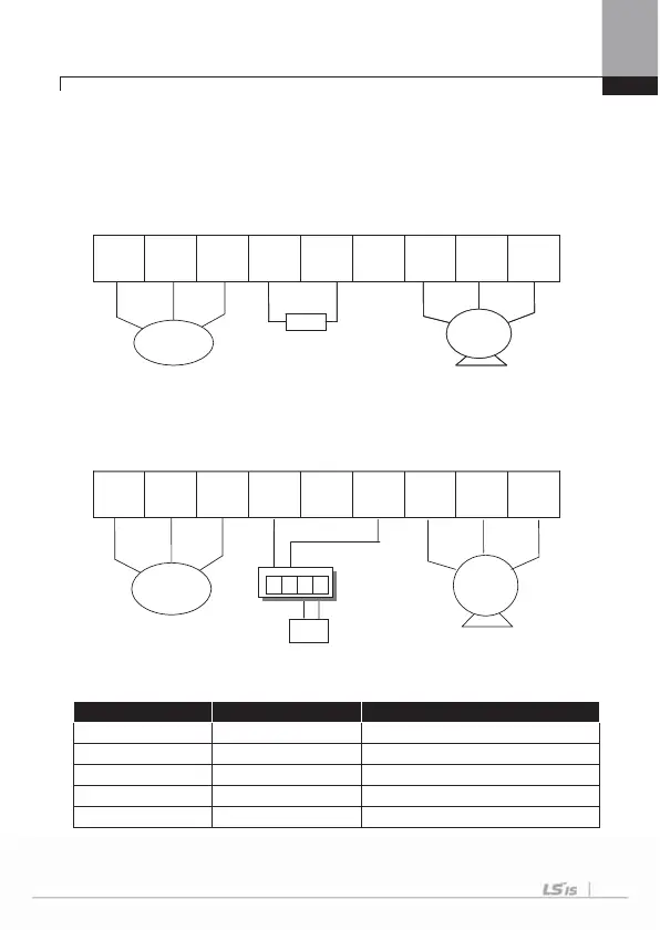
4.1.7 Terminals of main circuit
1) 0.75 ~ 22 kW (200V/400V)
(1) Built-in dynamic braking unit used
Connect P(+) and B terminal of inverter to the dynamic braking unit when built-in
dynamic unit is used.
R(L1) S(L2) T(L3) P(+) B N(-) U V W
(2) Optional dynamic braking unit used
Connects P(+) terminal of inverter to P/(+) terminal of the dynamic braking unit and
N(-) terminal of inverter to N/(-) terminal of the dynamic braking unit. B terminal of
inverter is not used.
R(L1) S(L2) T(L3) P(+) B N(-) U V W
ۡ
ۡ
ۡ
ۡ
ۡ
ۡ
Terminal Symbol Terminal Name Description
R(L1),S(L2),T(L3) AC power supply input Connects normal AC input
P(+) (+) DC voltage terminal (+) DC link voltage terminal
N(-) (-) DC voltage terminal (-) DC link voltage terminal.
P(+),B Dynamic brake resistor Connects dynamic brake resistor.
U,V,W Inverter output Connects the 3 phase induction motor
Dynamic
Braking Unit
3 Phase
AC Input
Motor
Dynamic Brake
Resistor
DBR
Dynamic Brake
Resistor
3 Phase
C Input
Motor
DB
P
N
B1 B2

 Loading...


