Chapter 7 Checking and Troubleshooting
G
7-4
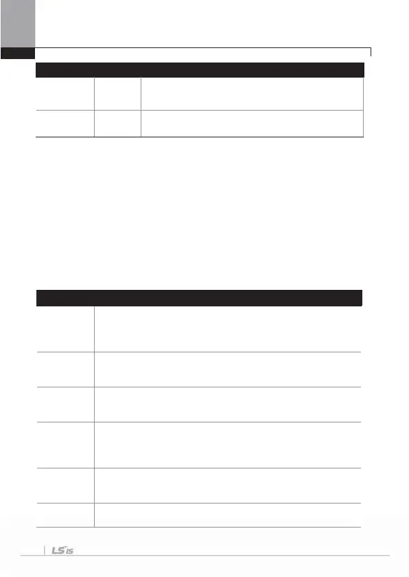
Type Category Details
Option Trip-3 Latch
When the option gets out of the option slot No. 3 after it was
inserted during power supply or when communication is not
available with the inverter.
I/O Board Trip Latch
When the basic and insulated I/O boards are disconnected
or have a fault of connection.
Note) Level : automatically terminates when the failure is solved. This is not saved in
the failure history.
Latch : terminates when the reset signals are input after the failure is solved.
Fatal : The failure state terminates when you cut the power supply to the inverter
and then supply power again with the internal charging lamp is turned off
after the failure is solved.
Failure history will be saved and the fault output signal will be outputted.
If the inverter keeps the fault state after re-inputting of power, please
contact to sales representative of LSIS.
* The functions of the save of failure history and the output of fault signal could not be
operated in case the functions have not set or the inverter got damaged seriously.
7.1.2 Alarm functions
G
Type Description
Over Load
An alarm signal is released in case of overload to the motor. Operation
resumes if you set PRT-17 at 1. If signals are necessary for the output
contact point, No. 4 overload is selected among the functions of
OUT31~33.
Under Load
Set PRT-25 at 1 if an alarm is necessary for an underload situation. As
the output signal, No. 6 Under Load is selected among the functions of
OUT31~33.
Inv Over
Load
An alarm is released if time equal to 60% of the level at which the
inverter IOLT functions is accumulated. As the output signal, No. 5 IOL
is selected among the functions of OUT31~33.
Lost
Command
An alarm signal can be released as well when PRT-12 Lost Cmd Mode
is 0. The alarm is released in a certain condition between PRT13~15.
As the output signal, No. 12 Lost Command is selected among the
functions of OUT31~33.
Fan Warning
An alarm is released if a problem is detected with the cooling fan with
PRT-79 FAN Trip Mode set at 1. As the output signal, No.8 Fan
Warning is selected among the functions of OUT31~33.
DB
Warn %ED
An alarm is released if the DB resistance consumption rate is above the
prescribed degree. The detection level is set at PRT-66.

 Loading...


