ٻ
ٻ
ٻ
ڞۃڼۋۏۀۍٻڌڋٻڡېۉھۏۄۊۉڼۇٻڮڼہۀۏ۔ٻ
G
10-3
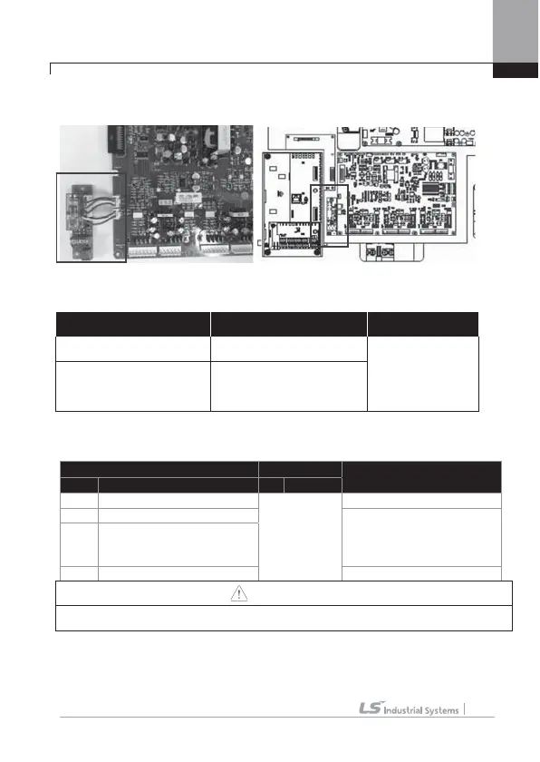
3) 185~375KW Product Installation
- Connect main SMPS board and safety option board with Safety Wire as above.
4) Description of Safety Function Terminal
5) Signal Terminal Block Wiring Standard
Te rm i na l Wire Thickness
Electrical Standard
variety Name
m2 AWG
24SE Safety Input Power
0.33~1.25mm2
(16~22 AWG)
Shield Type
Twisted-pare Wire
24Vdc , Max. 10mA
SE Safety Input 1(SFT1) Short : Safety Function Stop(24SE-SE or
SP)
Open : Safety Function Operation (24SE-
SP or SP)
SP Safety Input 2(SFT2)
R+,S
- Complete Output Relay Safety Features DC24V, 5A below (B contact)
Caution
The length of wiring safety input terminal is not used for more than 30m.
Safety Function can malfunction during operation.
ٻ
ٻ
24SE – SE (SFT1) 24S – SP (SFT2) SR + SR-
Short : Normal operation Short : Normal operation
B Contact Relay
Output Terminal
Open : Safety Trip (output
disconnect)
Open : Safety Trip (output
disconnect)

 Loading...


