Chapter 4 Wiring
4-16
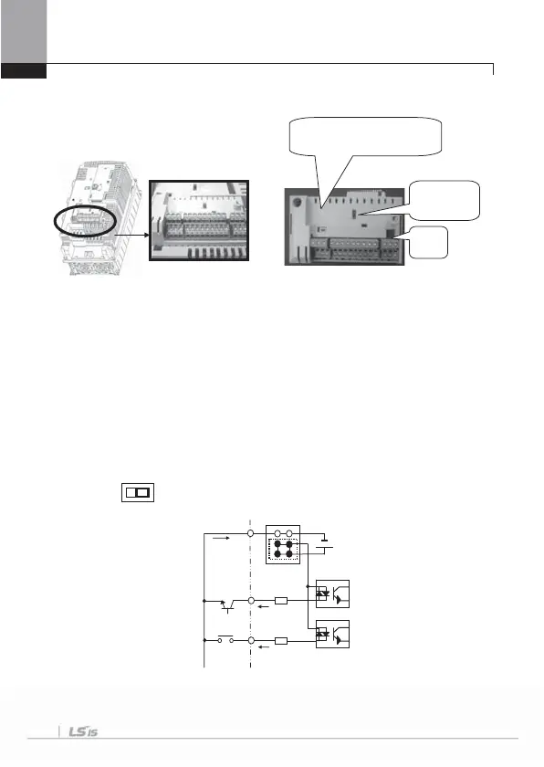
4.1.9 Control terminal line diagram (Basic I/O terminal block, below 22kW)
1) How to set NPN (Sink)/PNP (Source)
iS7 serves 2 sequence input terminals of control circuit: NPN mode (Sink mode)
and PNP mode (Source mode). It is possible to change the logic of input terminal with
NPN mode (Sink mode) and PNP mode (Source mode) by using NPN (Sink)/PNP
(Source) set terminal. Each mode connecting methods are follows.
(1) NPN mode (Sink mode)
Set NPN (Sink)/PNP (Source) switch into NPN. CM (24V GND) is common terminal of
contact point input signal. Initial set of Factory default is NPN mode (Sink mode).
I / PTC
set terminal
TR
NPN (Sink)
/PNP (Source) set terminal
Inner source
24V
CM (24G)
P1
FX
P2 (RX)
NPN
PNP
NPN mode (Sink mode)

 Loading...


