Chapter 4 Wiring
4-21
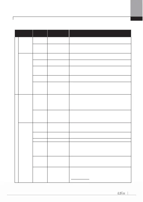
4.1.11 Control circuit terminal
1) Contact point start function selection
Type
Terminal
Symbol
Terminal Name Terminal Description
Input Signal
Contact
point start
functon
selection
P1~P8
Multi-function
input1~8
Available by defining as multi-function input
CM
Sequence
common terminal
Common terminal of the contact point input terminal
(note : In case of Basic I/O, common terminal is different
from the 5G common terminal)
Analog
Frequency
VR(+)
Frequency setting
Power (+) terminal
Power supply for analog frequency setting
Maximum output is +12V, 100mA.
VR(-)
Frequency setting
powe
(-) terminal
Power supply for analog frequency setting
Maximum output is -12V, 100mA.
V1
Frequency setting
(voltage)
Becomes set frequency with input of DC -10~10V.
Unipolar 0~+10[V]),Biopolar(-10[V] ~10[V])
input resistance 20kȍ
I1
Frequency setting
(current)
Becomes set frequency with input of DC 0~20m
input resistance 249ȍ
5G
Frequency setting
common terminal
Common terminal of analog frequency setting signal and
analog voltage and current terminals
(
note :
In case Basic I/O, common terminal are different
from the CM common terminal.)
Output Signal
Analog
A01
Multi-function
analog voltage
output terminal
Select the one among Output frequency, Output current,
DC voltage.
- Ouput voltage : 0~10V
- Maximum output voltage : 10V
- Maximum output current: 10mA
A02
Multi-function
analog current
output terminal
Select the one among Output frequency, Output
current,Output voltage, DC voltage.
- Output current: 4~20mA (0~20mA)
- Maximum output current: 20mA
Contact
Point
Q1
Multi-function
terminal
(open collector)
DC 26V, below 100mA
EG
Common terminal
for open collector
External power supply common earth terminal of the
open collector
24 Exterior 24Vpower Maximum output current: 150m
A1, B1, C1 Fault signal output
Protection function is activated to break output.
(below AC 250V 5A, DC 30V 5A)
- Fault signal : A1-C1 electrified (B1-C1 unelectrified)
- Normal signal : B1-C1 electrified (A1-C1 unelectrified)
A2, C2
Multi-function
relay 2 output A
contact point
Output the signal while running. User defined multi-
function output terminal.
(below AC 250V 5A, DC 30V 5A)
S+,S-, CM
RS-485 signal
input terminal
RS-485 signal line
(Refer to ‘Communication Function’ contained in iS7 User
Manual. You can download it from LSIS website.
(http://www.lsis.biz
). This provided manual is the simple
version of iS7 User Manual.

 Loading...


