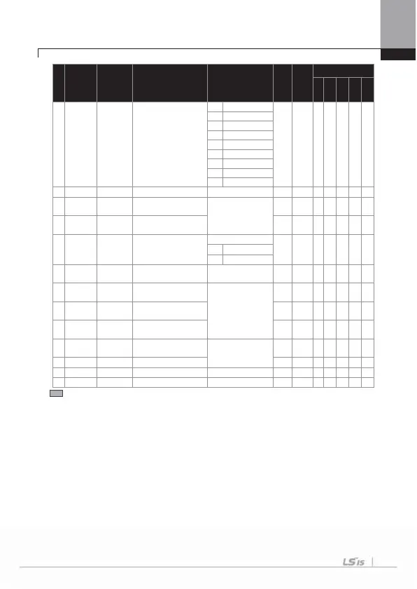
Chapter 8 Table of Functions
G
8-23
No. Comm. No.
Function
Display
Name Setting Range
Initial
Value
Shift in
Operation
Control Mode
V/
SL
VC
SLT
VCT
-- - -
2
Trip
- - -----
30 Lost Ke
pad
31 DB Warn%ED
32 ENC Tune
33 ENC Di
34 On/Off Control
3
BR Control
36 KEB Operatin
37 Fire Mode
41
0h162
DO Statu
multi-function output monitoring - 000 X
- - - - -
50
0h1632
DO On
Dela
multi-function output ON delay
0 ~ 100 [s]
0.00 O
O
O
OOO
51
0h1633
DO Off
Dela
multi-function output OFF delay 0.00 O
O
O
OOO
52
0h1634
DO
NC/NO
Sel
multi-function output contact point
selection
Q1,Relay2,Relay1
000 X
O
O
OOO
0
A contact point (NO
1
B contact point (NC
53
0h1635
TripOut
OnDl
failure output ON delay
0 ~ 100 [s]
0.00 O
O
O
OOO
54
0h1636
TripOut
OffDl
failure output OFF delay
0 ~ 100.00 [s]
0.00 O
O
O
OOO
55
0h1637
TimerOn
Dela
timer ON delay 0.00 O
O
O
OOO
56
0h1638
TimerOff
Dela
timer OFF delay 0.00 O
O
O
OOO
57
0h1639
FDT
Frequenc
detection frequency
0 ~ max. freq.[Hz]
30.00 O
O
O
OOO
5
0h163
FDT Band
detection frequency width 10.00
O
O
OOO
5
0h163B TD Level
detection torque amoun
0
150 [%]
100
XX
O
X
O
60
0h163
TD Band
detection torque width
0
10 [%]
5.0
XX
O
X
O
* The grey code refers to hidden code, emerging only in case of setting of the code.
G
G
G
G
G
G
G
G
G
G
G

 Loading...


