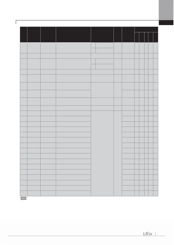
Chapter 8 Table of Functions
G
8-35
No. Comm. No.
Function
Display
Name Setting Range
Initial
Value
Shift in
Operation
Control Mode
V/F
SL
VC
SLT
VCT
1 Aux
2 Main
36
0h1A24
Auto Ch Time auto change time
0 ~ 99:00[min]
72:00 O O O O X X
38
0h1A26
Interlock interlock selection
0 No
0 : No O O O O X X
1 Ye s
39
0h1A27
Interlock DT interlock movement delay time
0.1 ~ 360.0 [s]
5.0 O O O O X X
40
0h1A28
Actual Pr Diff
auxiliary motor movement pressure
difference
0 ~ 100 [%]
2 O O O O X X
41
0h1A29
Aux Acc Time
main motor accelerating time when
number of
um
s decreases
0 ~ 600.0 [s]
2.0
O O O O X X
42
0h1A2A
Aux Dec Time
main motor decelerating time when
number of pumps increases
O O O O X X
5
Note37)
0h1A3A
PLC LED
Status
PLC option LED status
-
- O O O O O O
59
0h1A3B
PLC S/W Ver PLC option card S/W version
-
1.X O O O O O O
60
0h1A3C
PLC Wr Data 1
PLC write data 1
0 ~ FFFF[Hex]
0000
O O O O O O
61
0h1A3D
PLC Wr Data 2
PLC write data 2
O O O O O O
62
0h1A3E
PLC Wr Data 3
PLC write data 3
O O O O O O
63
0h1A3F
PLC Wr Data 4
PLC write data 4
O O O O O O
64
0h1A40
PLC Wr Data 5
PLC write data
O O O O O O
65
0h1A41
PLC Wr Data 6
PLC write data 6
O O O O O O
66
0h1A42
PLC Wr Data 7
PLC write data 7
O O O O O O
67
0h1A43
PLC Wr Data 8
PLC write data
O O O O O O
76
0h1A4C
PLC Rd Data 1
PLC read data 1 O O O O O O
77
0h1A4D
PLC Rd Data 2
PLC read data
O O O O O O
78
0h1A4E
PLC Rd Data 3
PLC read data 3
O O O O O O
79
0h1A4F
PLC Rd Data 4
PLC read data 4
O O O O O O
80
0h1A50
PLC Rd Data 5
PLC read data
O O O O O O
81
0h1A51
PLC Rd Data 6
PLC read data 6
O O O O O O
82
0h1A52
PLC Rd Data 7
PLC read data 7
O O O O O O
83
0h1A53
PLC Rd Data 8
PLC read data
O O O O O O
* The grey code refers to hidden code, emerging only in case of setting of the code.
Note 35)
APO-01~14 codes are displayed only when the encoder board is mounted.
Note 36)
APO-20~42 codes are displayed only when APP-01 (App Mode) is set as “MMC”.
Note 37)
APO-58~83 codes are displayed only when PLC option board is mounted.

 Loading...


