Chapter 4 Wiring
4-13
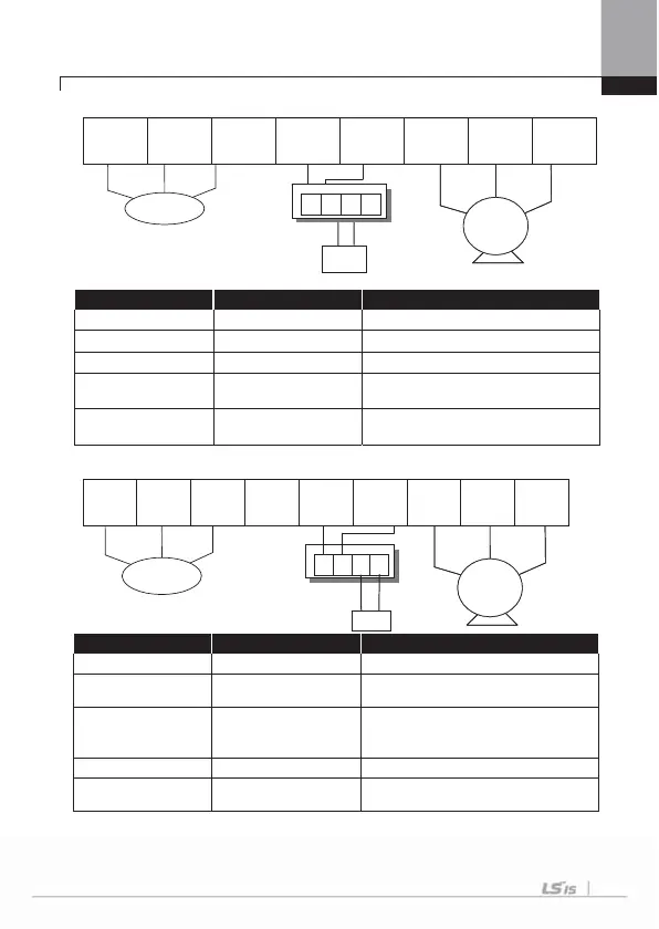
3) 90 ~ 160 kW (400V)
R(L1) S(L2) T(L3) P2(+) N(-) U V W
Terminal Symbol Terminal Name Description
R(L1), S(L2), T(L3) AC power supply input Connects normal AC input
P(+) (+)DC voltage ternimal (+)DC link voltage terminal
N(-) (-)DC voltage terminal ( - )DC link voltage terminal
P(+), N(-)
External brake unit
connection
Voltage terminal connecting Dynamic
brake unit.
U, V, W Inverter output
Connects the 3-phase induction
motor.
4) 280 ~ 375 kW (400V)
R(L1) S(L2) T(L3) P1(+) P2 N(-) U V W
Terminal Symbol Terminal Name Description
R(L1), S(L2), T(L3) AC power supply input Connects normal AC input
P1(+) (+)DC voltage terminal
(+)DC link voltage terminal,
It is located in front of DCL terminal.
P2, N(-)
Dynamic brake unit
connection,
DC common terminal
1)
Voltage terminal connecting Dynamic
brake unit, DC common terminal
N(-) (-)DC voltage terminal (-)DC link voltage terminal.
U, V, W Inverter output
Connects the 3-phase induction
motor.
1)
When using this terminal as a DC common, special considerations are required.
Be sure to consult with our sales representative.
Motor
Dynamic
brake unit
DBR
Dynamic
brake resistor
3 Phase
AC Input
P N B1
B2
Motor
3 Phase
AC Input
DBU
P
N
B1
B2
DBR

 Loading...


