Chapter 4 Wiring
4-19
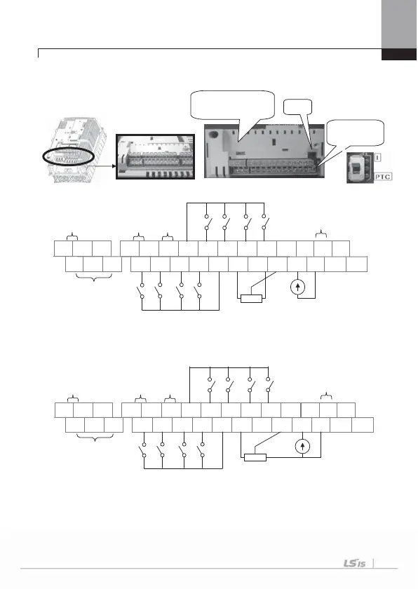
4.1.10 Control terminal line diagram
(Insulated I/O terminal block, above 30kW)
1) 30~375kW (Insulated I/O)
TR terminal is RS485 communication terminal resistor (120 ).
We recommend the potentiometer for 1/2W, 1k .
NPN (Sink)/PNP
(Source) Set terminal
I / PTC
Set terminal
T
S- C2
5G
S+
CM
P4 P3
P2
P1
CM
24 EG
Q1
NC A2
AO1
C1
AO2 CM I1 V1 VR- VR+
CM P8
P7
P6 P5
B1
A1
RS485
0~10V Output
0~20mA Output
4~20mA Output
Relay2
(Normal
Open)
Relay1
(Normal
Open)
Open
Collector
Output
24V
power
supply
Digital contact point
input (NPN/PNP,
Sink/Source mode
support)
In case of
analog voltage
input with
potentiometer
(0V~+10V input)
In case of
analog
current
input
(4~20 mA
input)
AO2
0~10V Output
S- C2
5G
S+
CM
P4 P3
P2
P1
CM
24 EG
Q1
NC A2
AO1
C1
CM I1 V1 VR- VR+
CM P8
P7
P6 P5
B1
A1
RS485
Port
0~20mA Output
4~20mA Output
Relay2
(Normal
Open)
Relay1
(Normal Open)
Open
Collector
Output
24V
power
su
l
Digital contact point
input
(NPN/PNP,
Sink/Source mode
support)
In case of
analog voltage
input with
potentiometer
(-10V~+10V input)
In case of
analog
current
input
(4~20 mA
input)

 Loading...


