EasyManua.ls Logo

LSIS XEC-DP64H User Manual

LSIS XEC-DP64H
315 pages
To Next Page IconTo Next Page
To Previous Page IconTo Previous Page
Page #121 background imageLoading...
Page #121 background image
Chapter 5 Positioning Instructions
5 - 22
5.2.8 Position Speed Switching Instruction
This is operation by switching the axis operating by the current position control into speed control by
the position/speed switching instruction (PVT instruction). For details, refer to 3.1.5.
(1) Position/Speed Switching Instruction (PTV)
[
[Area Setting]
Operand
Description
Setting range
Data size
sl Slot No. of positioning module XGB is fixed at 0 WORD
ax
Axis to give instruction
0 (axis X) or 1 (axis Y)
WORD
[Flag Set]
Flag Description Device number
Error If the value of ax gets out of the range F110
(a) Function
• This instruction is giving the position/speed control switching instruction to XGB built-in positioning.
• The axis designated as ax at the rising edge in the input condition is switched from the position
operation to speed operation.
• The current position which was output during the previous speed control operation is not initialized
to 0 and only the control method is switched to speed control with the operation continued.
(b) Error
If the value designated as ax (instruction axis) is other than 0 and 1, the error flag (F110) is set
and the instruction is not executed.
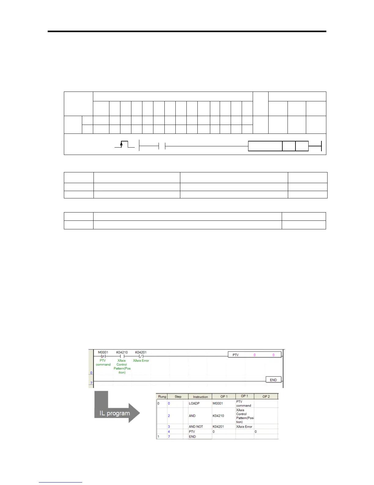
(2) Example of Use of the Instruction
The position/speed control switching instruction is described with the example of the following
program.
(a) Example of the Program
Instruction
Areas available
Step
Flag
PMK F L T C S Z D.x R.x
Cons
tant
U N D R
Error
(F110)
Zero
(F111)
Carry
(F112)
PTV
sl
-
-
-
-
-
-
-
-
-
-
-
-
-
4~7 - -
ax
-
-
-
-
-
-
-
-
-
PTV
COMMAND
PTV
sl
ax

Table of Contents

Questions and Answers:

LSIS XEC-DP64H Specifications

General IconGeneral
BrandLSIS
ModelXEC-DP64H
CategoryController
LanguageEnglish

Summary

XGB Built-in Positioning

Safety Instruction

Crucial safety guidelines to be followed before operating the product.

Chapter 1 General

Provides general information about the positioning function, including purpose and features.

Chapter 2 General Specification

Provides general specifications for the XGB series, including environmental and immunity details.

Chapter 3 Before Positioning

Explains various positioning functions, parameters, and operation data.

Chapter 4 Positioning Check

Outlines the procedure for testing XGB positioning operation before use.

Chapter 5 Positioning Instructions

Provides detailed explanations for various positioning instructions like Origin Return, Direct Start, etc.

Chapter 6 Positioning Monitoring Package

Introduces the XGB positioning monitoring package for status monitoring and test operation.

Chapter 7 Program Examples of Positioning

Provides practical program examples for various positioning functions.

Chapter 8 Troubleshooting Procedure

Outlines basic steps for troubleshooting errors in XGB PLC and positioning functions.

Appendix 1 List of Error Codes

Details specific error codes related to the XGB positioning function.

Appendix 2 Positioning Instruction and K area List

Provides a list of dedicated K areas for positioning parameters and instructions.

Appendix 3 Motor Wiring Example

Illustrates wiring examples for connecting XGB PLC to servo motors.

Appendix 4 Dimension

Provides dimensional drawings for standard XGB main units (XBM-DN/DR series).

Related product manuals