Chapter 7 Program Examples of Positioning
7 - 12
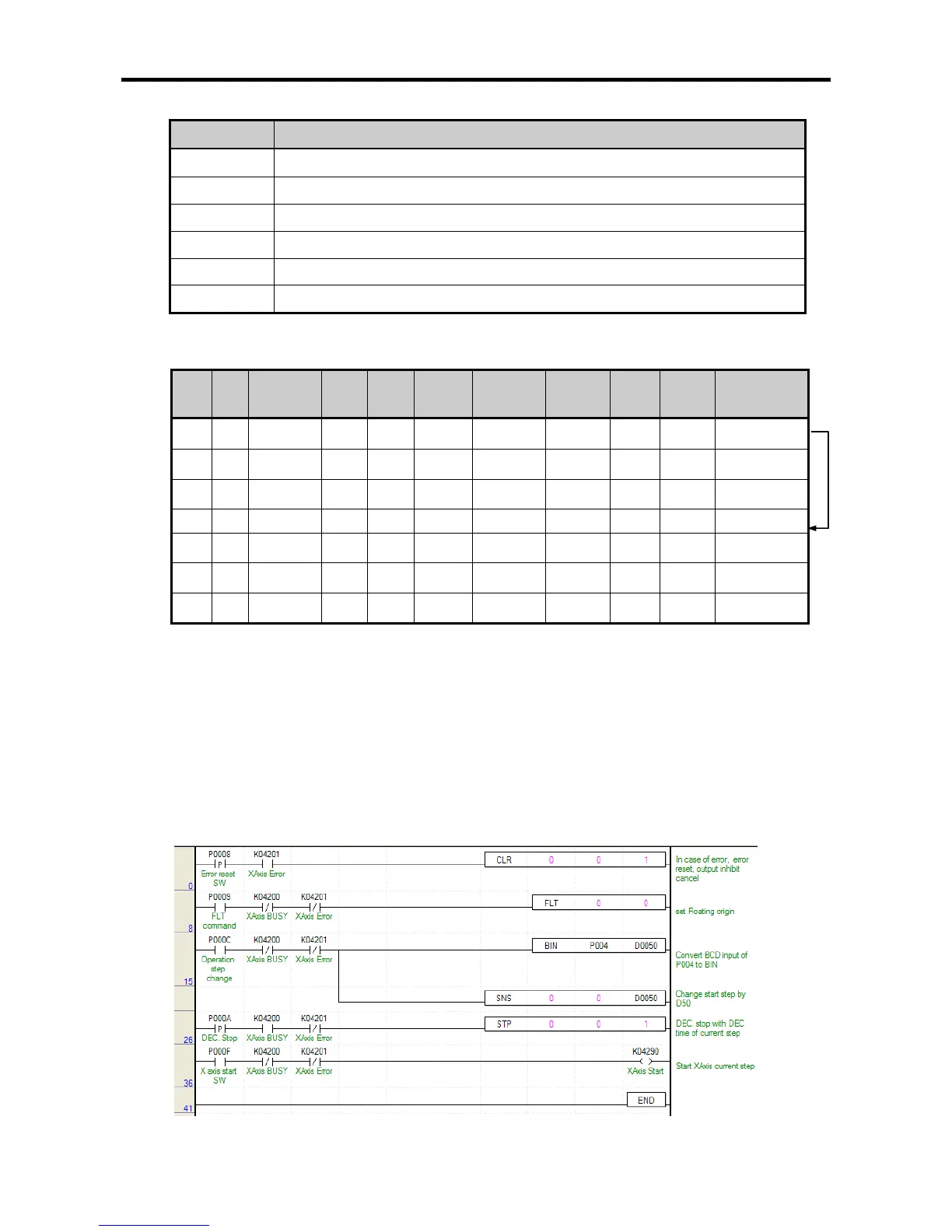
(a) Devices Used
Device Description
%IX0.1.0 Error reset, output inhibition cancel switch
%IX0.1.1 Floating origin switch
%IX0.1.4 Operation step change switch
%IX0.1.7 axis X start switch
%KX6720 Signal during axis X operation
%KX6721 Error signal of axis X
(3) Operation Data Setting
Step
No.
coordi
nates
Control pattern
Operatio
n pattern
Operatio
n type
Repeat step
Target position
[pulse]
M code
Acc./Dec.
No.
Operation
speed
[pls/s]
Dwell time
[㎳]
1
Abs
olute
Position
control
End Single 0 10,000 0 1 1,000
100
2
Abs
olute
Position
control
End Single 0 20,000 0 1 1,500 100
3
Abs
olute
Position
control
End Single 0 30,000 0 1 2,000 100
10
Abs
olute
Position
control
End Single 0 50,000 0 1 1,000 100
11
Abs
olute
Position
control
End Single 0 60,000 0 1 1,500 100
12
Abs
olute
Position
control
End Single 0 70,000 0 1 2,000 100
(4) Operation Sequence
• P0009/%IX0.1.1 (floating origin) switch On : set as the floating origin at the current position.
• BCD/SNS_STEP switch input: enters the operation step to change in P004(enters 10 in this
example).
• P000C/%IX0.1.4(operation step change) switch On : the currently operating step changes into 10.
• P000F/%IX0.1.7(axis X start) On : indirect start is conducted with the changed step (10).
7.2.5 Setting of Operation Step/Speed Control
• The program example of conducting speed control by setting the operation step is as follows.
(1) XBM/XBC