EasyManua.ls Logo

LSIS XEC-DP64H User Manual

LSIS XEC-DP64H
315 pages
To Next Page IconTo Next Page
To Previous Page IconTo Previous Page
Page #135 background imageLoading...
Page #135 background image
Chapter 5 Positioning Instructions
5 - 36
5.2.14 Positioning Speed Override Instruction
The positioning speed override instruction (PSO) is changing the operation speed of the axis during
current positioning operation at the specific position set in the instruction. For details, refer to 3.1.10.
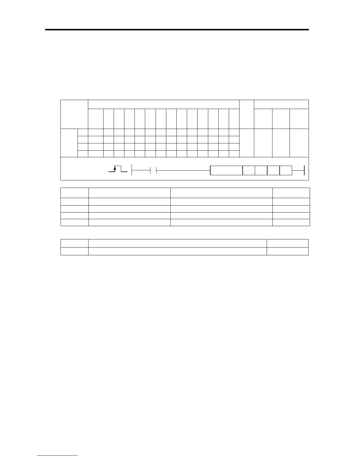
(1) Positioning speed override instruction (PSO)
[Area Setting]
Operand
Description
Setting range
Data size
sl Slot No. of positioning module XGB is fixed at 0 WORD
ax
Axis to give instruction
0 (axis X) or 1 (axis Y)
WORD
n1
Position to change the speed
-2,147,483,648 ~ 2,147,483,647
DINT
n2
Operation speed to change
0 ~ 100,000[pps]
DWORD
[Flag Set]
Flag Description Device number
Error If the value of ax gets out of the range F110
(a) Function
This instruction is giving the positioning speed override instruction to XGB built-in positioning.
The positioning speed override is executed at the axis designated as ax at the rising edge of the
input condition, and if the current position reaches the position set in n1 during operation, the
current operation speed is overridden to the speed set in n2.
The positioning speed override instruction is available in the deceleration and acceleration
sections and if the positioning speed override is executed during deceleration or dwell, no error
code is issued, but the instruction is not executed either.
(b) Error
If the value designated as ax (instruction axis) is other than 0 and 1, the error flag (F110) is set
and the instruction is not executed.
Instruction
Areas available
Step
Flag
PMK F L T C S Z D.x R.x
con
stan
t
U N D R
Error
(F110)
Zero
(F111)
Carry
(F112)
PSO
sl
-
-
-
-
-
-
-
-
-
-
-
-
-
4~7 - -
ax - - - - - - - - -
n1 - - - - - - - - -
n2
-
-
-
-
-
-
-
-
-
PSO
COMMAND
PSO
sl ax n1 n2

Table of Contents

Questions and Answers:

LSIS XEC-DP64H Specifications

General IconGeneral
BrandLSIS
ModelXEC-DP64H
CategoryController
LanguageEnglish

Summary

XGB Built-in Positioning

Safety Instruction

Crucial safety guidelines to be followed before operating the product.

Chapter 1 General

Provides general information about the positioning function, including purpose and features.

Chapter 2 General Specification

Provides general specifications for the XGB series, including environmental and immunity details.

Chapter 3 Before Positioning

Explains various positioning functions, parameters, and operation data.

Chapter 4 Positioning Check

Outlines the procedure for testing XGB positioning operation before use.

Chapter 5 Positioning Instructions

Provides detailed explanations for various positioning instructions like Origin Return, Direct Start, etc.

Chapter 6 Positioning Monitoring Package

Introduces the XGB positioning monitoring package for status monitoring and test operation.

Chapter 7 Program Examples of Positioning

Provides practical program examples for various positioning functions.

Chapter 8 Troubleshooting Procedure

Outlines basic steps for troubleshooting errors in XGB PLC and positioning functions.

Appendix 1 List of Error Codes

Details specific error codes related to the XGB positioning function.

Appendix 2 Positioning Instruction and K area List

Provides a list of dedicated K areas for positioning parameters and instructions.

Appendix 3 Motor Wiring Example

Illustrates wiring examples for connecting XGB PLC to servo motors.

Appendix 4 Dimension

Provides dimensional drawings for standard XGB main units (XBM-DN/DR series).

Related product manuals