Chapter 5 Positioning Instructions
5 - 49
5.3 Positioning Function Blocks (for XEC)
5.3.1 General for Function Block
In the XEC PLC, the input/output variables and their functions which are applied commonly for all the
function blocks used for internal positioning are as follows..
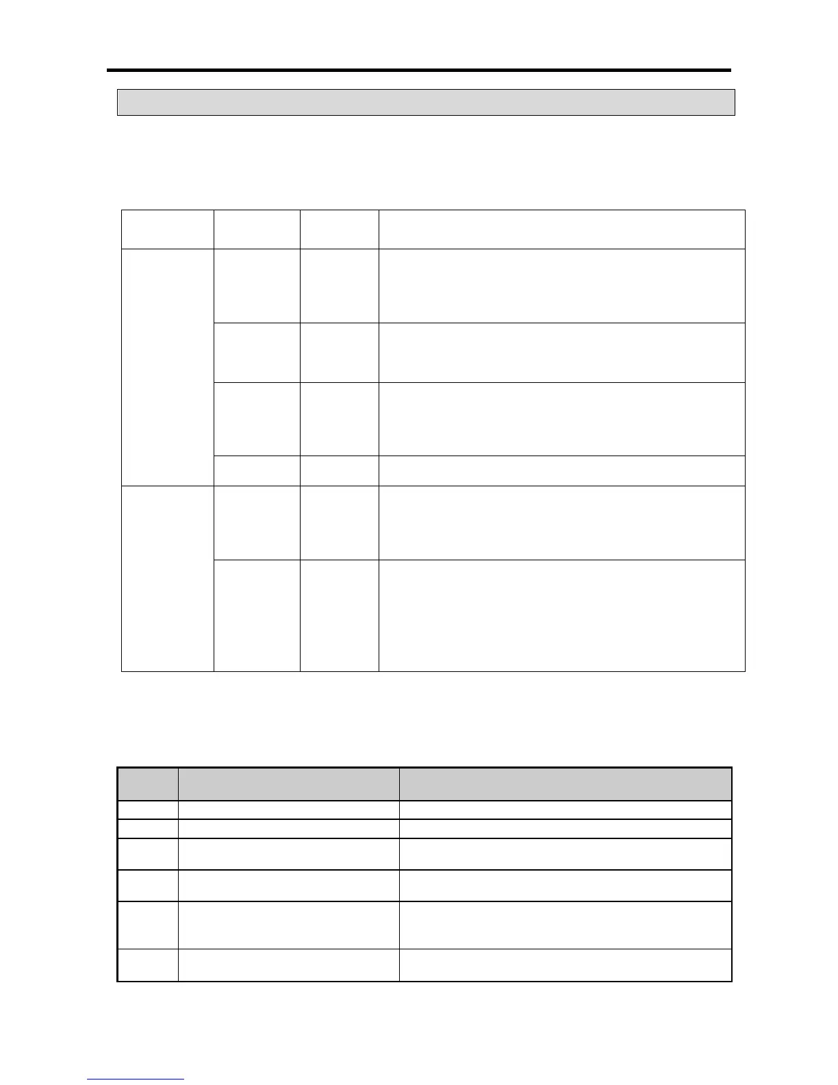
Classification Variable
Data Type Description
Input
Variables
REQ BOOL
•Request for function block execution
- If the condition in connection with this area is
satisfied during the software running and 0→1
(edge or level), the function block is executed.
- This area is for setting up the number of the base
where the positioning module is mounted. (In the
internal positioning of XGB, fix this to 0.)
- This area is for setting up the number of the slot
where the positioning module is mounted. (In the
internal positioning of XGB, fix this to 0.)
•Number of the axis in use
- X-axis: 0, Y-axis: 1
Output
Variables
DONE BOOL
•Indicates completion of the function block execution
- If the function block is executed without error,
“1” is outputted and maintained until the next
execution. If erroneous, “0” is outputted.
- This area indicates the number of the error
occurred in the start-up of the function block.
(The errors occurred during operation are
indicated in the K area which outputs error
Other I/O variables excluding the common variables presented in the above table are described
below.
(1) Common Error Codes for Function Block
The types and description of the common error codes which may occur in the starting up of the function
blocks related with internal positioning are as follows.
Error
Error Type Countermeasures
0 Function block normally executed -
1 Base No. exceeded setting range Set the base No. to “0” for internal positioning.
3 Slot No. exceeded setting range Set the slot No. to “0” for internal positioning.
6 Axis range No. exceeded setting range
Adjust the axis No. within the allowable range of the
function block
(0: X-axis, 1: Y-axis)
10
A new function block was executed
while the previous instruction
Modify the program so that a new function block can be
executed after completion of the previous instruction.
11
Set-
up auxiliary input value exceeded
allowable range
Adjust the value within the allowable range.
For other error code, see “Appendix 1. Error Code List.”