Chapter 5 Positioning Instructions
5 - 77
5.3.12 Speed Synchronization Function Block
•This instruction (APM_SSSB) is for the operation at synchronized speed at the preset rate with the
axis set up in the instruction as the sub-axis when the main axis is started up. For details of speed
synchronization function, see 3.1.8.
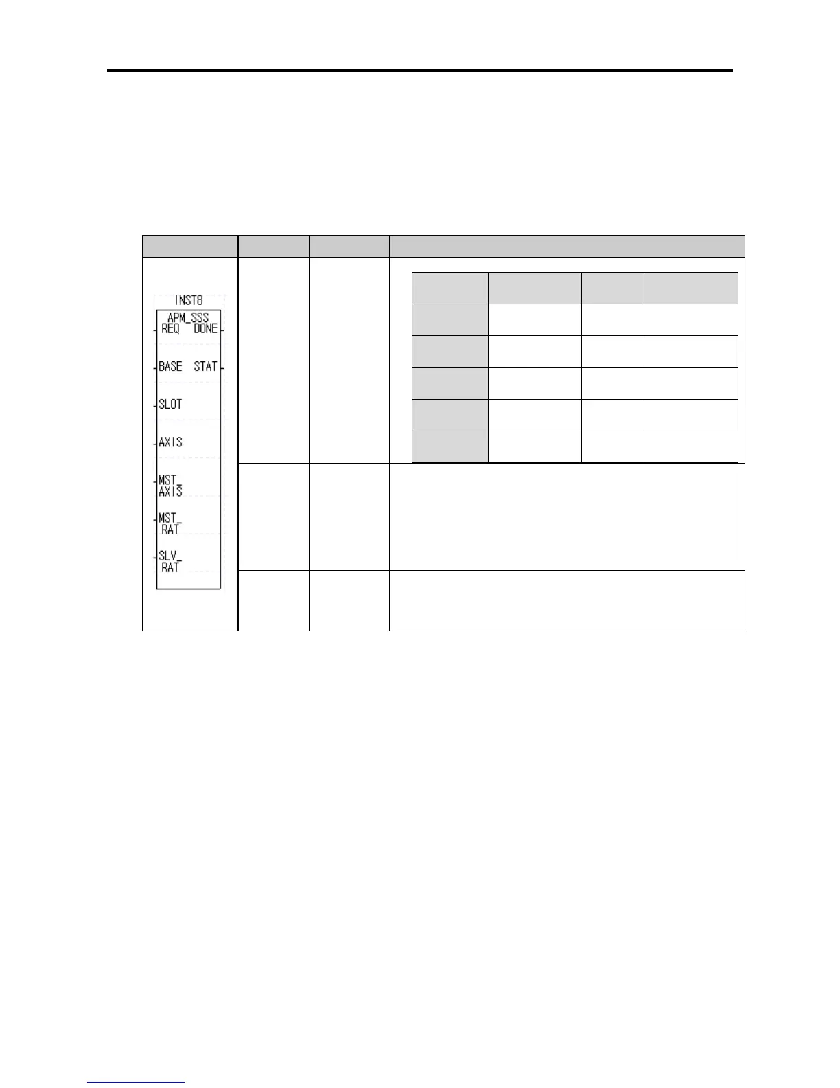
(1) Speed Synchronization Start-up Instruction (APM_SSSB)
Form Variable Data Type Description
MST_
AXIS
USINT
SLV_RAT
UINT
Speed ratio of sub-axis
● Setting range: 1 ~ 10,000(0.01 ~ 100.00%)
DELAY
USINT
Sub-axis delay time
● Setting range: 1 ~ 10(1 ~ 10ms)
(a) Function
•This is the instruction for executing speed synchronized start-up to the XGB internal positioning.
•At the rising edge of the input condition, speed position synchronized start-up instruction is
executed with the AXIS as the sub-axis and the axis designated in the MST_AXIS as the main
axis.
•When the instruction is executed, the sub-axis does not output real pulse (at this time, the in-
operation-state flag (X-axis: %KX6720, Y-axis: %KX6880) of the sub-axis is ON), and when the
main axis MST_AXI starts, the sub-axis starts at the speed synchronization ratio set up in the
AXIS.
•The synchronization ratio which can be set up in the SLV_RAT is 0.01% ~ 100.00% (setting value
1 ~ 10,000). If the setting exceeds this range, error code 356 is created.
•The DELAY time is the time required for the speed of the sub-axis to reach the present speed of
the main axis. In the XGB internal positioning function, for speed synchronization control, the
present speed of the main axis is detected at every 500 ㎲ to control the speed of the sub-axis.
Here, if the speed of the sub-axis is synchronized to that of the main axis without delay time, the
motor and drive may receive excessive impact.
For example, when the speed synchronization ratio is 100.00% and delay time is 5[ms], and if the
present speed of the main axis is 10,000[pps], XGB internal positioning adjusts the speed of the
sub-axis so that it’s speed is the same as that of the main axis after 5[㎳] at every 500[㎲].
When the delay time is longer, the synchronization time delay between the main and sub-axes is
longer but the output pulse is more stable. If there is the possibility that the motor may lose
synchronism, set the delay time longer.
•The range of the delay time that can be set up in DELAY n2 is 1 ~ 10[㎳]. If this range is exceeded,
error code 357 is generated.