EasyManua.ls Logo

LSIS XEC-DP64H User Manual

LSIS XEC-DP64H
315 pages
To Next Page IconTo Next Page
To Previous Page IconTo Previous Page
Page #108 background imageLoading...
Page #108 background image
Chapter 5 Positioning Instructions
5 - 9
5.2.3 Direct Starting Instruction
Direct starting refers to designating the operation data of the target position and speed from the
positioning instruction (DST instruction) for operation without using the setting of the step set in the
positioning operation data.
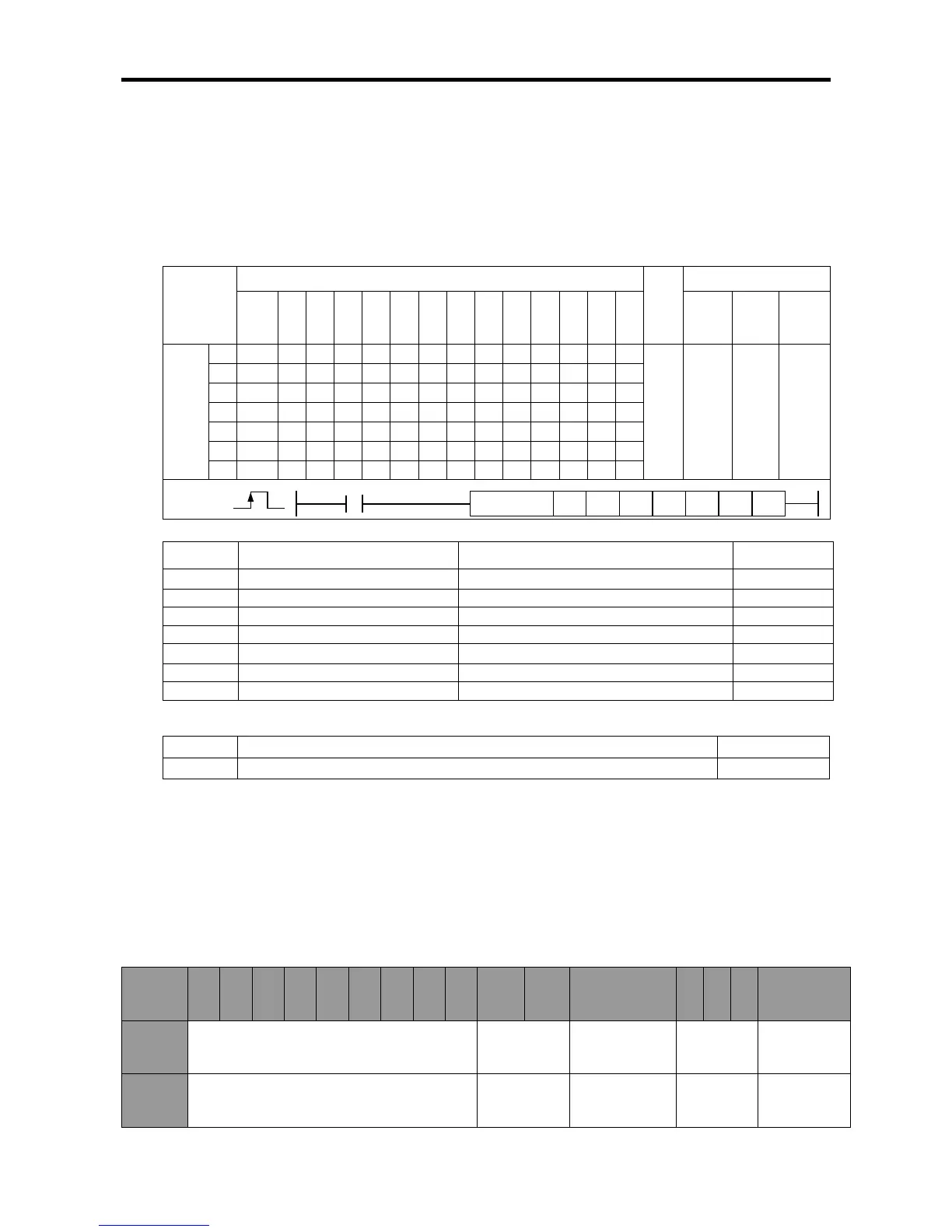
(1) Direct Starting Instruction (DST)
[
[Area Setting]
Operand
Description
Setting range
Data size
sl Slot No. of positioning module XGB is fixed at 0 WORD
ax
Axis to give instruction
0 (axis X) or 1 (axis Y)
WORD
n1
Target position
-2,147,483,648~2,147,483,647[Pulse]
DINT
n2
Target speed
1~100,000[pps]
DWORD
n3 dwell time
0~50,000[]
WORD
n4
M code number
M code (0~65,535)
WORD
n5
Control word
See ‘(a) function’
WORD
[Flag Set]
Flag Description Device number
Error If the value of ax gets out of the range F110
(a) Function
This instruction is for directly ordering the start to XGB built-in positioning.
This instruction carries out direct starting of the axis designated as ax of XGB positioning at the
rising edge of input condition.
If the instruction is executed, positioning operation is started by using the target position set in n1,
the target speed set in n2, the dwell time set in n3, and the M code number set in n4 instead of the
operation data set in the step number (axis X:K426, axis Y:K436 word) of area K.
The absolute/Incremental coordinates, position/speed control and acceleration/deceleration
pattern number are fixed by the setting of each bit of the control word set as n5.
Instruction
Areas available
Step
Flag
PMK F L T C S Z D.x R.x
con
stan
t
U N D R
Error
(F110)
Zero
(F111)
Carry
(F112)
DST
sl
-
-
-
-
-
-
-
-
-
-
-
-
-
4~7 - -
ax
-
-
-
-
-
-
-
-
-
n1
-
-
-
-
-
-
-
-
-
n2 - - - - - - - - -
n3
-
-
-
-
-
-
-
-
-
n4
-
-
-
-
-
-
-
-
-
n5
-
-
-
-
-
-
-
-
-
DST
COMMAND
DST
n2
n3
n4
n5
sl
ax
n1
Bit
number
F E D C B A 9 8 7 6 5 4 3 2 1 0
Setting
item
Not used Acc./dec. time
coordinates
setting
Not used
control
method
Setting
range
-
0: 1, 1:2
2:3, 3:4
0: absolute
1: ncremental
-
0: position
1: speed

Table of Contents

Questions and Answers:

LSIS XEC-DP64H Specifications

General IconGeneral
BrandLSIS
ModelXEC-DP64H
CategoryController
LanguageEnglish

Summary

XGB Built-in Positioning

Safety Instruction

Crucial safety guidelines to be followed before operating the product.

Chapter 1 General

Provides general information about the positioning function, including purpose and features.

Chapter 2 General Specification

Provides general specifications for the XGB series, including environmental and immunity details.

Chapter 3 Before Positioning

Explains various positioning functions, parameters, and operation data.

Chapter 4 Positioning Check

Outlines the procedure for testing XGB positioning operation before use.

Chapter 5 Positioning Instructions

Provides detailed explanations for various positioning instructions like Origin Return, Direct Start, etc.

Chapter 6 Positioning Monitoring Package

Introduces the XGB positioning monitoring package for status monitoring and test operation.

Chapter 7 Program Examples of Positioning

Provides practical program examples for various positioning functions.

Chapter 8 Troubleshooting Procedure

Outlines basic steps for troubleshooting errors in XGB PLC and positioning functions.

Appendix 1 List of Error Codes

Details specific error codes related to the XGB positioning function.

Appendix 2 Positioning Instruction and K area List

Provides a list of dedicated K areas for positioning parameters and instructions.

Appendix 3 Motor Wiring Example

Illustrates wiring examples for connecting XGB PLC to servo motors.

Appendix 4 Dimension

Provides dimensional drawings for standard XGB main units (XBM-DN/DR series).

Related product manuals