EasyManua.ls Logo

LSIS XEC-DP64H User Manual

LSIS XEC-DP64H
315 pages
To Next Page IconTo Next Page
To Previous Page IconTo Previous Page
Page #109 background imageLoading...
Page #109 background image
Chapter 5 Positioning Instructions
5 - 10
The instruction only sets the item of the operation data, and the basic parameter items related to
the operation such as the bias speed and speed limit are fixed in the positioning basic parameters.
If you use the DST instruction, the operation pattern is fixed as End operation, and the operation
method is fixed as the single operation. But if continued operation or repeated operation is needed,
use indirect starting (IST instruction).
(b) Error
If the value designated as ax (instruction axis) is other than 0 and 1, the error flag (F110) is set
and the instruction is not executed.
This case if an error of execution of the instruction, so the error of positioning area K flag (axis
X:K4201, axis Y: K4301) does not turn On.
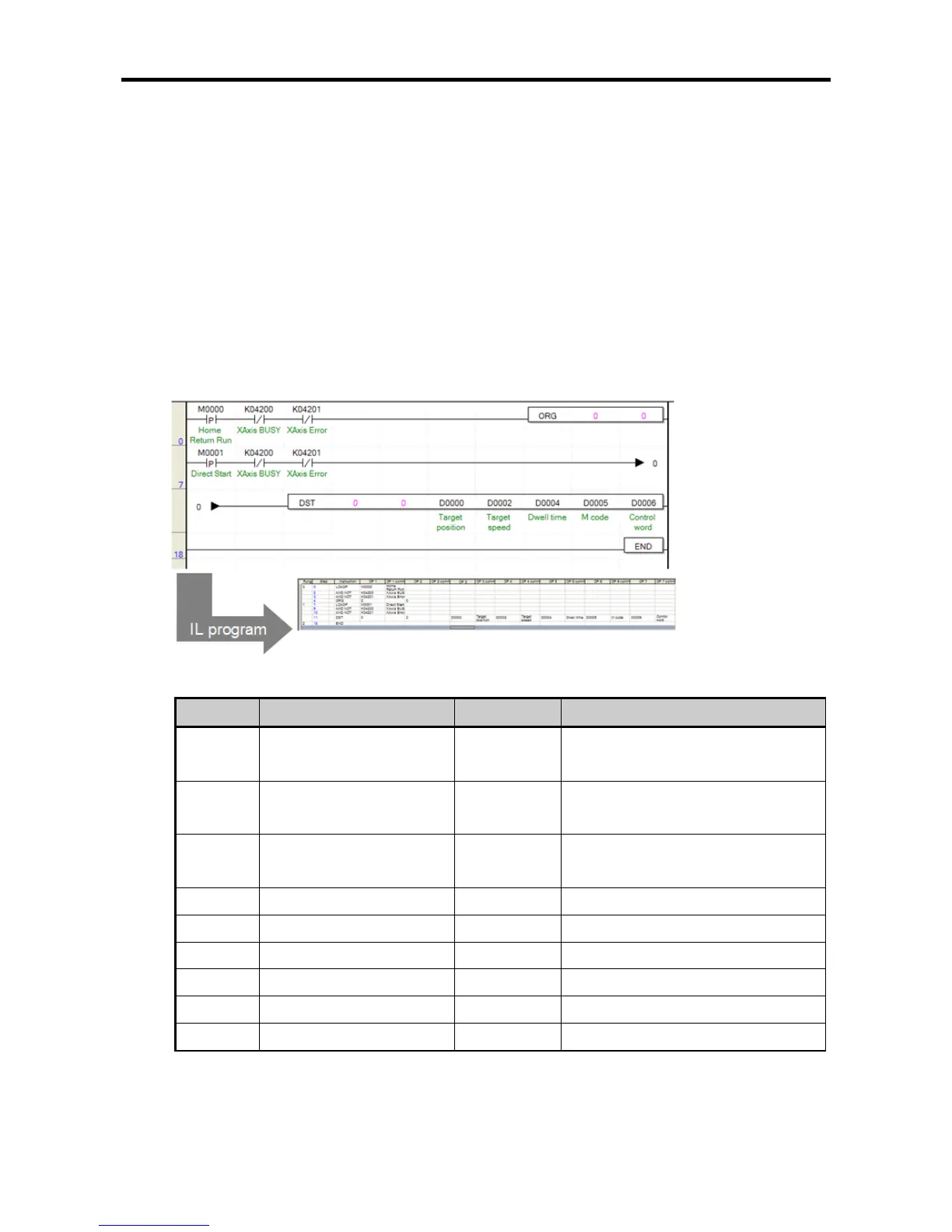
(2) Example of Use of the Instruction
Direct starting instruction is described with the example of the following program.
The example of use of the DST instruction is described on the basis of axis X.
(a) Example of the Program
(b) Device Used
Device
Description
Data size
Example of setting
M0000
axis X origin return
instruction signal
BIT -
M0001
axis X direct starting
instruction signal
BIT -
K4200
signal during axis X
operation
BIT -
K4201
axis X error
BIT
-
D0000
Target position
DINT
100,000
D0002
Target speed
DWORD
30,000
D0004
Dwell time
WORD
100
D0005
M code number
WORD
123
D0006
Control word
WORD
H’20
H`20 : Bit5~6 : 1 (No.2 acceleration/deceleration pattern), Bit 4 : 0 (absolute coordinates),
Bit0 : 0(position control)

Table of Contents

Questions and Answers:

LSIS XEC-DP64H Specifications

General IconGeneral
BrandLSIS
ModelXEC-DP64H
CategoryController
LanguageEnglish

Summary

XGB Built-in Positioning

Safety Instruction

Crucial safety guidelines to be followed before operating the product.

Chapter 1 General

Provides general information about the positioning function, including purpose and features.

Chapter 2 General Specification

Provides general specifications for the XGB series, including environmental and immunity details.

Chapter 3 Before Positioning

Explains various positioning functions, parameters, and operation data.

Chapter 4 Positioning Check

Outlines the procedure for testing XGB positioning operation before use.

Chapter 5 Positioning Instructions

Provides detailed explanations for various positioning instructions like Origin Return, Direct Start, etc.

Chapter 6 Positioning Monitoring Package

Introduces the XGB positioning monitoring package for status monitoring and test operation.

Chapter 7 Program Examples of Positioning

Provides practical program examples for various positioning functions.

Chapter 8 Troubleshooting Procedure

Outlines basic steps for troubleshooting errors in XGB PLC and positioning functions.

Appendix 1 List of Error Codes

Details specific error codes related to the XGB positioning function.

Appendix 2 Positioning Instruction and K area List

Provides a list of dedicated K areas for positioning parameters and instructions.

Appendix 3 Motor Wiring Example

Illustrates wiring examples for connecting XGB PLC to servo motors.

Appendix 4 Dimension

Provides dimensional drawings for standard XGB main units (XBM-DN/DR series).

Related product manuals