EasyManua.ls Logo

LSIS XEC-DP64H User Manual

LSIS XEC-DP64H
315 pages
To Next Page IconTo Next Page
To Previous Page IconTo Previous Page
Page #163 background imageLoading...
Page #163 background image
Chapter 5 Positioning Instructions
5 - 64
5.3.7 Simultaneous Start-up Function Block
•Simultaneous start-up instruction (APM_SST) starts the steps of the 2 axes designated in the
instruction simultaneously. For details, see 3.1.7.
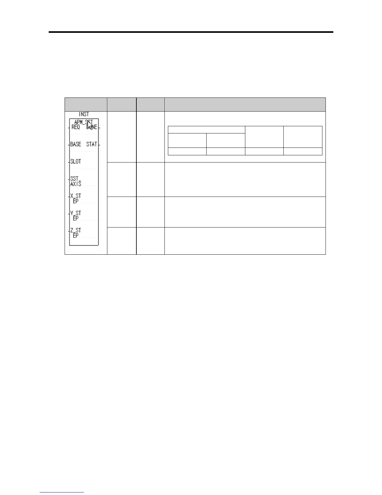
(1) Simultaneous Start-up Instruction(APM_SST)
Form Variable
Data
Type
Description
SST_
AXIS
USINT
● Simultaneous start-up operation axis
Axis information
Setting
Value
Operation
axis
Y-
axis(BIT1)
X-
axis(BIT0)
ON(1)
ON(1)
3
X,Y
X_STEP UINT
Operation step No.
● Setting range: 0 ~ 80
Y_STEP UINT
Operation Step No.
● Setting range: 0 ~ 80
Z_STEP UINT Dummy variable
(a) Function
•This instruction gives simultaneous start-up reference to the XGB internal positioning.
•At the rising edge of the input condition, the 2 axes of the XGB positioning are started up
simultaneously. See 3.1.7 for the difference between using simultaneous start up instruction and
continuous start up of 2 axes continuously with PLC ladder programming.
•When this instruction is executed, of the XGB’s positioning axes, X and Y axes are simultaneously
started up using the operation data set up at X_STEP and Y_STEP for X-axis and Y-axis,
respectively. Here, since the XGB internal positioning has no Z-axis, the set value of Z_STEP does
not have influence on the operation.

Table of Contents

Questions and Answers:

LSIS XEC-DP64H Specifications

General IconGeneral
BrandLSIS
ModelXEC-DP64H
CategoryController
LanguageEnglish

Summary

XGB Built-in Positioning

Safety Instruction

Crucial safety guidelines to be followed before operating the product.

Chapter 1 General

Provides general information about the positioning function, including purpose and features.

Chapter 2 General Specification

Provides general specifications for the XGB series, including environmental and immunity details.

Chapter 3 Before Positioning

Explains various positioning functions, parameters, and operation data.

Chapter 4 Positioning Check

Outlines the procedure for testing XGB positioning operation before use.

Chapter 5 Positioning Instructions

Provides detailed explanations for various positioning instructions like Origin Return, Direct Start, etc.

Chapter 6 Positioning Monitoring Package

Introduces the XGB positioning monitoring package for status monitoring and test operation.

Chapter 7 Program Examples of Positioning

Provides practical program examples for various positioning functions.

Chapter 8 Troubleshooting Procedure

Outlines basic steps for troubleshooting errors in XGB PLC and positioning functions.

Appendix 1 List of Error Codes

Details specific error codes related to the XGB positioning function.

Appendix 2 Positioning Instruction and K area List

Provides a list of dedicated K areas for positioning parameters and instructions.

Appendix 3 Motor Wiring Example

Illustrates wiring examples for connecting XGB PLC to servo motors.

Appendix 4 Dimension

Provides dimensional drawings for standard XGB main units (XBM-DN/DR series).

Related product manuals