EasyManua.ls Logo

LSIS XEC-DP64H User Manual

LSIS XEC-DP64H
315 pages
To Next Page IconTo Next Page
To Previous Page IconTo Previous Page
Page #186 background imageLoading...
Page #186 background image
Chapter 5 Positioning Instructions
5 - 87
5.3.17 Start Step Number Change Function Block
•This instruction (APM_SNS) changes the number of the step to be operated.
(1) Start Step No. Change Instruction (APM_SNS)
Form Variable Data Type Description
STEP
UINT
Operation Step No.
● Setting range: 1 ~ 80
(a) Function
•This instruction provides start step change reference to the XGB internal positioning.
•At the rising edge of the input condition, the present step number of the axis designated to be AXIS
is changed to the step set up in the STEP.
•If the axis has been in operation when this instruction is given, error code 441 is generated and the
instruction is not executed. If the setting value in the STEP exceeds allowable range, error code
442 is generated and the instruction is not executed.
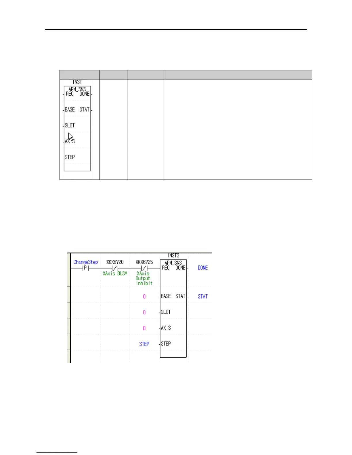
(2) Sample Instruction
(a) Sample Program
(b) Program Operation
•At the rising edge of the ‘operation step change’ signal used as the reference signal, the present
operation step No. of the positioning X-axis is changed to the step No. set up in the STEP.

Table of Contents

Questions and Answers:

LSIS XEC-DP64H Specifications

General IconGeneral
BrandLSIS
ModelXEC-DP64H
CategoryController
LanguageEnglish

Summary

XGB Built-in Positioning

Safety Instruction

Crucial safety guidelines to be followed before operating the product.

Chapter 1 General

Provides general information about the positioning function, including purpose and features.

Chapter 2 General Specification

Provides general specifications for the XGB series, including environmental and immunity details.

Chapter 3 Before Positioning

Explains various positioning functions, parameters, and operation data.

Chapter 4 Positioning Check

Outlines the procedure for testing XGB positioning operation before use.

Chapter 5 Positioning Instructions

Provides detailed explanations for various positioning instructions like Origin Return, Direct Start, etc.

Chapter 6 Positioning Monitoring Package

Introduces the XGB positioning monitoring package for status monitoring and test operation.

Chapter 7 Program Examples of Positioning

Provides practical program examples for various positioning functions.

Chapter 8 Troubleshooting Procedure

Outlines basic steps for troubleshooting errors in XGB PLC and positioning functions.

Appendix 1 List of Error Codes

Details specific error codes related to the XGB positioning function.

Appendix 2 Positioning Instruction and K area List

Provides a list of dedicated K areas for positioning parameters and instructions.

Appendix 3 Motor Wiring Example

Illustrates wiring examples for connecting XGB PLC to servo motors.

Appendix 4 Dimension

Provides dimensional drawings for standard XGB main units (XBM-DN/DR series).

Related product manuals