EasyManua.ls Logo

LSIS XEC-DP64H User Manual

LSIS XEC-DP64H
315 pages
To Next Page IconTo Next Page
To Previous Page IconTo Previous Page
Page #160 background imageLoading...
Page #160 background image
Chapter 5 Positioning Instructions
5 - 61
5.3.6 Linear Interpolation Start-up Function Block
•In linear interpolation start-up, both X and Y axes are used in the manner that the movement paths of
the 2 axes, from the start address (present stationary position) to the target address (position), is
linear.
•This method can be classified into absolute coordinates control and Incremental coordinates control.
For details, see 3.1.2.
•At the linear interpolation start-up instruction, the axis having greater movement for positioning
becomes the main axis automatically. If the 2 axes move the same distance, X-axis is set up as the
main axis.
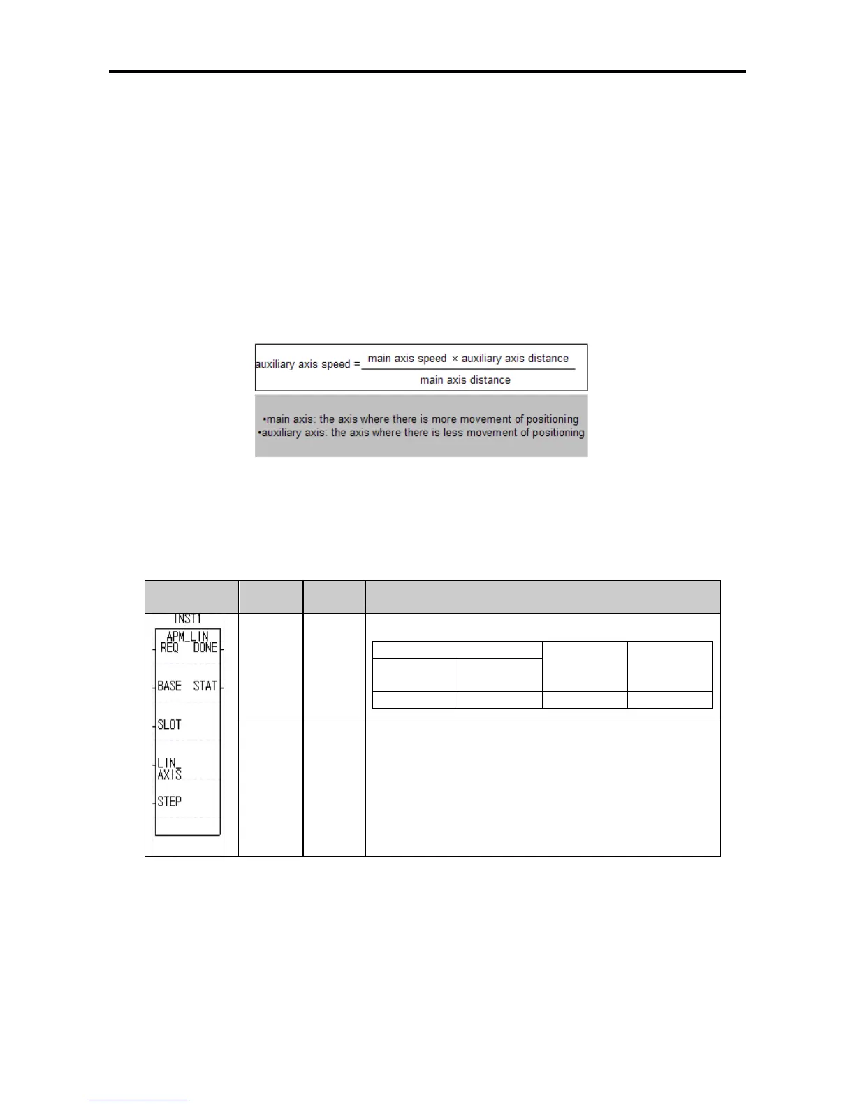
•Here, the velocity of the subsidiary axis does not follow the setting of the operation data. The
operation velocity, accelerating and decelerating times, and bias velocity are calculated automatically
with the formula below to perform the operation.
•The operation patterns available for linear interpolation are termination and continuous operation only.
If the interpolation operation is started when the main axis is set up to be continuous, the XGB
internal positioning does not trigger error and performs the operation of the main axis by changing it
to be continuous. If the sub-axis is set to be continuous, it does not affect linear interpolation.
(1) Linear Interpolation Start-up Instruction (APM_LIN)
Form Variable
Data
Type
Description
LIN_
AXIS
USINT
● Interpolation operation axis
Axis information
Setting
value
Operation
axis
Y-
axis(BIT1)
X-
axis(BIT0)
ON(1)
ON(1)
3
X,Y
STEP UINT
Operation step No.
● setting range: 0 ~ 80

Table of Contents

Questions and Answers:

LSIS XEC-DP64H Specifications

General IconGeneral
BrandLSIS
ModelXEC-DP64H
CategoryController
LanguageEnglish

Summary

XGB Built-in Positioning

Safety Instruction

Crucial safety guidelines to be followed before operating the product.

Chapter 1 General

Provides general information about the positioning function, including purpose and features.

Chapter 2 General Specification

Provides general specifications for the XGB series, including environmental and immunity details.

Chapter 3 Before Positioning

Explains various positioning functions, parameters, and operation data.

Chapter 4 Positioning Check

Outlines the procedure for testing XGB positioning operation before use.

Chapter 5 Positioning Instructions

Provides detailed explanations for various positioning instructions like Origin Return, Direct Start, etc.

Chapter 6 Positioning Monitoring Package

Introduces the XGB positioning monitoring package for status monitoring and test operation.

Chapter 7 Program Examples of Positioning

Provides practical program examples for various positioning functions.

Chapter 8 Troubleshooting Procedure

Outlines basic steps for troubleshooting errors in XGB PLC and positioning functions.

Appendix 1 List of Error Codes

Details specific error codes related to the XGB positioning function.

Appendix 2 Positioning Instruction and K area List

Provides a list of dedicated K areas for positioning parameters and instructions.

Appendix 3 Motor Wiring Example

Illustrates wiring examples for connecting XGB PLC to servo motors.

Appendix 4 Dimension

Provides dimensional drawings for standard XGB main units (XBM-DN/DR series).

Related product manuals