EasyManua.ls Logo

LSIS XEC-DP64H User Manual

LSIS XEC-DP64H
315 pages
To Next Page IconTo Next Page
To Previous Page IconTo Previous Page
Page #114 background imageLoading...
Page #114 background image
Chapter 5 Positioning Instructions
5 - 15
5.2.5 Straight Interpolation Starting Instruction
Straight interpolation starting refers to the operation so that the path of axes X and Y is straight from
the starting address (current stop location) to the target address (target address).
Straight interpolation control divides into control by absolute coordinates and Incremental coordinates.
For details, refer to 3.1.2.
When the instruction of straight interpolation starting is given, the axis where there is more movement
is designated as the main axis. If the movements are equal, axis X is the main axis.
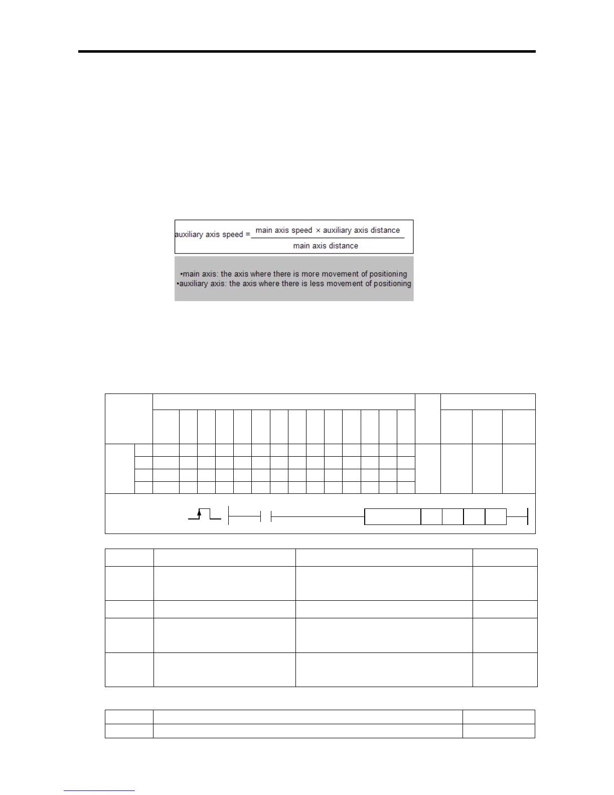
The speed of the auxiliary axis does not follow the setting of the operation data, but conducts
operation by calculating the operation speed, acceleration time, deceleration time, and bias speed
automatically by the following operations.
The operation pattern that can use straight interpolation operation is limited to End and Continued
operation. If the main axis is set as Continued and the interpolation operation is started, no error is
issued in XGB built-in positioning but the operation pattern of the main axis is changed into
Continued. If the auxiliary axis is set as Continued, it does not affect the straight interpolation.
(1) Straight Interpolation Starting Instruction (LIN)
A
[Area Setting]
Operand
Description
Setting range
Data size
sl
Slot number of positioning
module
XGB is fixed at 0 WORD
ax
Axis to give instruction
0 (axis X) or 1 (axis Y) WORD
n1
Step number to carry out
straight interpolation
0~30(standard), 0~80(advanced) WORD
n2
Set the axis to car
ry out
straight interpolation
XGB is set at 3 WORD
[Flag Set]
Flag Description Device number
Error If the value of ax gets out of the range F110
Instruction
Areas available
Step
Flag
PMK F L T C S Z D.x R.x
con
stan
t
U N D R
Error
(F110)
Zero
(F111)
Carry
(F112)
LIN
sl
-
-
-
-
-
-
-
-
-
-
-
-
-
4~7 - -
ax
-
-
-
-
-
-
-
-
-
n1
-
-
-
-
-
-
-
-
-
n2
-
-
-
-
-
-
-
-
-
LIN
COMMAND
LIN
sl ax
n1
n2

Table of Contents

Questions and Answers:

LSIS XEC-DP64H Specifications

General IconGeneral
BrandLSIS
ModelXEC-DP64H
CategoryController
LanguageEnglish

Summary

XGB Built-in Positioning

Safety Instruction

Crucial safety guidelines to be followed before operating the product.

Chapter 1 General

Provides general information about the positioning function, including purpose and features.

Chapter 2 General Specification

Provides general specifications for the XGB series, including environmental and immunity details.

Chapter 3 Before Positioning

Explains various positioning functions, parameters, and operation data.

Chapter 4 Positioning Check

Outlines the procedure for testing XGB positioning operation before use.

Chapter 5 Positioning Instructions

Provides detailed explanations for various positioning instructions like Origin Return, Direct Start, etc.

Chapter 6 Positioning Monitoring Package

Introduces the XGB positioning monitoring package for status monitoring and test operation.

Chapter 7 Program Examples of Positioning

Provides practical program examples for various positioning functions.

Chapter 8 Troubleshooting Procedure

Outlines basic steps for troubleshooting errors in XGB PLC and positioning functions.

Appendix 1 List of Error Codes

Details specific error codes related to the XGB positioning function.

Appendix 2 Positioning Instruction and K area List

Provides a list of dedicated K areas for positioning parameters and instructions.

Appendix 3 Motor Wiring Example

Illustrates wiring examples for connecting XGB PLC to servo motors.

Appendix 4 Dimension

Provides dimensional drawings for standard XGB main units (XBM-DN/DR series).

Related product manuals