EasyManua.ls Logo

LSIS XEC-DP64H User Manual

LSIS XEC-DP64H
315 pages
To Next Page IconTo Next Page
To Previous Page IconTo Previous Page
Page #117 background imageLoading...
Page #117 background image
Chapter 5 Positioning Instructions
5 - 18
5.2.6 Simultaneous Starting Instruction
The simultaneous starting instruction (SST instruction) is for simultaneously starting the steps of the
axes set in the instruction. For details, refer to 3.1.7.
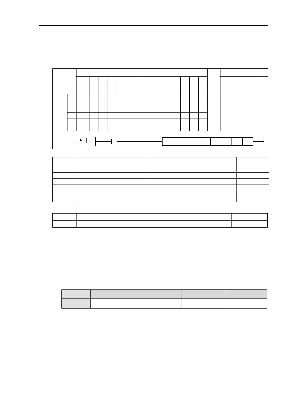
(1) simultaneous starting instruction (SST)
[
[Area Setting]
Operand
Description
Setting range
Data size
sl
Slot No. of positioning module
XGB is fixed at 0
WORD
ax
Axis to give instruction
0 (axis X) or 1 (axis Y)
WORD
n1
axis X Step No.
0~30(standard), 0~80(advanced)
WORD
n2
axis Y Step No.
0~30(standard), 0~80(advanced)
WORD
n3
axis Z Step No.
Not used
WORD
n4
Axis setting
XGB is set at 3
WORD
[Flag Set]
Flag Description Device number
Error If the value of ax gets out of the range F110
(a) Function
This function is for giving the simultaneous starting instruction to XGB built-in positioning
simultaneous starting.
The two axes of XGB positioning are simultaneously started at the rising edge of the input
condition. (For the difference between using the simultaneous starting instruction and starting the
two axes consecutively in the PLC ladder program, refer to 3.1.7.)
When the instruction is executed, axis X and axis Y simultaneously start by using the operation
data of the step number set in n1 and n2 respectively. XGB built-in positioning does not have axis
Z, so the set value of n3 does not affect the operation.
Axis setting of n4 sets the axis to carry out simultaneous starting by bit as follows.
Bit No. 15 ~ 3 2 1 0
Setting Not used Axis Z (XGB not used) axis Y axis X
- Each bit refers to the axis to start straight interpolation. In the case of XGB built-in positioning,
only axis X and axis Y are available, so n4 should be fixed at 3. Otherwise, error code 296 is
issued and operation does not occur.
(b) Error
If the value designated as ax (instruction axis) is other than 0 and 1, the error flag (F110) is set
and the instruction is not executed.
Since this case if an error of execution of the instruction, the error in positioning area K error
flag(axis X:K4201, axis Y: K4301) does not turn On..
If the set value of the starting step number gets out of the settable range, instruction Error
Flag(F110) is not set, the error flag of positioning area K (axis X:K4201, axis Y: K4301) turns On,
and the operation does not occur.
Instruction
Areas available
Step
Flag
PMK F L T C S Z D.x R.x
con
stan
t
U N D R
Error
(F110)
Zero
(F111)
Carry
(F112)
SST
sl
-
-
-
-
-
-
-
-
-
-
-
-
-
4~7 - -
ax
-
-
-
-
-
-
-
-
-
n1 - - - - - - - - -
n2
-
-
-
-
-
-
-
-
-
n3
-
-
-
-
-
-
-
-
-
n4
-
-
-
-
-
-
-
-
-
SST
COMMAND
SST
n2
n3 n4
sl ax
n1

Table of Contents

Questions and Answers:

LSIS XEC-DP64H Specifications

General IconGeneral
BrandLSIS
ModelXEC-DP64H
CategoryController
LanguageEnglish

Summary

XGB Built-in Positioning

Safety Instruction

Crucial safety guidelines to be followed before operating the product.

Chapter 1 General

Provides general information about the positioning function, including purpose and features.

Chapter 2 General Specification

Provides general specifications for the XGB series, including environmental and immunity details.

Chapter 3 Before Positioning

Explains various positioning functions, parameters, and operation data.

Chapter 4 Positioning Check

Outlines the procedure for testing XGB positioning operation before use.

Chapter 5 Positioning Instructions

Provides detailed explanations for various positioning instructions like Origin Return, Direct Start, etc.

Chapter 6 Positioning Monitoring Package

Introduces the XGB positioning monitoring package for status monitoring and test operation.

Chapter 7 Program Examples of Positioning

Provides practical program examples for various positioning functions.

Chapter 8 Troubleshooting Procedure

Outlines basic steps for troubleshooting errors in XGB PLC and positioning functions.

Appendix 1 List of Error Codes

Details specific error codes related to the XGB positioning function.

Appendix 2 Positioning Instruction and K area List

Provides a list of dedicated K areas for positioning parameters and instructions.

Appendix 3 Motor Wiring Example

Illustrates wiring examples for connecting XGB PLC to servo motors.

Appendix 4 Dimension

Provides dimensional drawings for standard XGB main units (XBM-DN/DR series).

Related product manuals