Chapter 4 Positioning Check
4- 1
Chapter 4 Positioning Check
This Chapter describes how to test the operation test to check whether the positioning function is well performed
before the XGB positioning function is used.
4.1 The Sequence of Positioning Check
This is for checking whether the XGB positioning operation is normally performed by carrying out normal
and reverse direction jog operation. The sequence is as follows.
(1) Power Off
• Distribution is needed to check the XGB positioning operation.
Before distribution, turn off XGB.
• Be sure to check whether the PWR LED of XGB is off before moving on to the next step.
(2) Input Signal Distribution
• Distribute the input signals needed to check the operation as follows.
• Do not connect the output signal line to the motor driver. If there is a problem with the PLC hardware,
connecting to the motor driver might lead to malfunction or damage to the equipment.
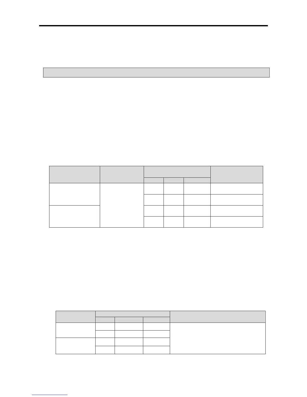
Input Signal
Contact Point
Type
Contact Point No.
Remark
XBC XEC
Jog normal direction
switch
Contact point
normally open (A)
Axis X P0010 %IX0.0.16
Contact point
randomly selected
Axis Y P0011 %IX0.0.17
Contact point
randomly selected
Jog reverse direction
switch
Axis X P0012 %IX0.0.18
Contact point
randomly selected
Axis Y P0013 %IX0.0.19
Contact point
randomly selected
(3) Making the Program for Operation Check
• Make the program for checking the operation by using XG5000. For the details and making of the
program, see ‘4.2 Making of the
Program for Operation Check.’
(4) Power Supply and Program Writing
• If you have finished making the program, supply power to XGB PLC, and use XGB as the parameter
and the program.
(5) Input Contact Point Operation Check
• Before switching the operation mode of the PLC to RUN, check the normal operation of the input
contact point as follows.
Input Signal
Contact No.
Operation Check
XBC XEC
Jog normal
direction
Axis X P0010 %IX0.0.16
• Check whether the LED of the contact
point turns on while the switch is ON and
the value of the contact point changes into
1 in the device monitor of XG5000.
Axis Y P0011 %IX0.0.17
Jog reverse
direction
Axis X P0012 %IX0.0.18
Axis Y P0013 %IX0.0.19
• If the device doesn’t work as described in the table above, there might be a problem with the LED or
the input hardware, so contact the customer center.