Chapter 3 Before positioning
3- 58
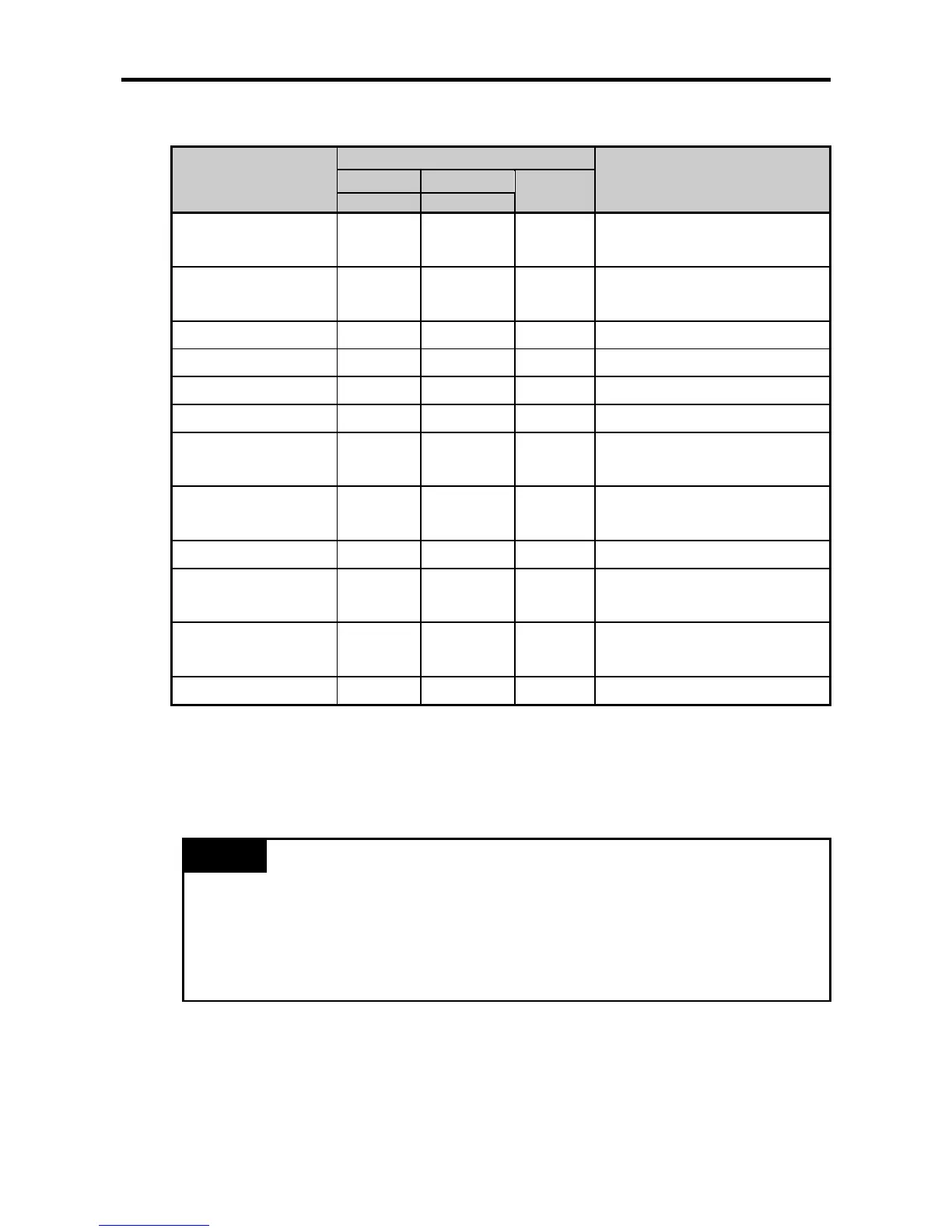
(b) In case of XBM/XBC (Step 01)
Variables
Device area
Status
Axis X Axis Y
properties
Address Address
Step 01 target position
%KD265 %KD415
Double
word
Step 01 operation speed
%KD267 %KD417
Double
word
Step 01 dwell time
%KW536 %KW836
Word
Step 01 M code number
%KW537 %KW837
Word
Step 01 operation method
%KX8608 %KX13408
Bit
Step 01 control method
%KX8609 %KX13409
Bit
Step 01 operation pattern
(Low)
%KX8610 %KX13410
Bit
Step 01 operation pattern
(High)
%KX8611 %KX13411
Bit
Step 01 coordinates
%KX8612 %KX13412
Bit
Step 01 acc./dec. number
(Low)
%KX8614 %KX13414
Bit
Step 01 acc./dec. number
(High)
%KX8615 %KX13415
Bit
Step 01 coordinates
%KW539 %KW839
Word
• The table above shows the area K for positioning of the operation step #1. You can change the
operation data without setting the parameters by changing the value of the corresponding area K.
• If you want to permanently preserve the operation data of the changed area K, apply the data of
current area K to the built-in parameter area by using the applied instruction (WRT instruction,
APM_WRT instruction).
Remark
• Note that area K for positioning is initialized if you cut the power and re-supply power or if you
change the operation mode without executing the WRT instruction after changing the value of
area K.
• The variable of area K for each step can be used more conveniently by using the variable
registration function of XG5000. For the positioning monitor registration, see the manual of
XG5000.