Chapter 5 Positioning Instructions
5 - 47
5.2.22 Pulse Width Modulation
• Pulse Width Modulation is to operate On/Off output in designated Off duty rate and Output cycle.
(1) Pulse width Modulation (PWM)
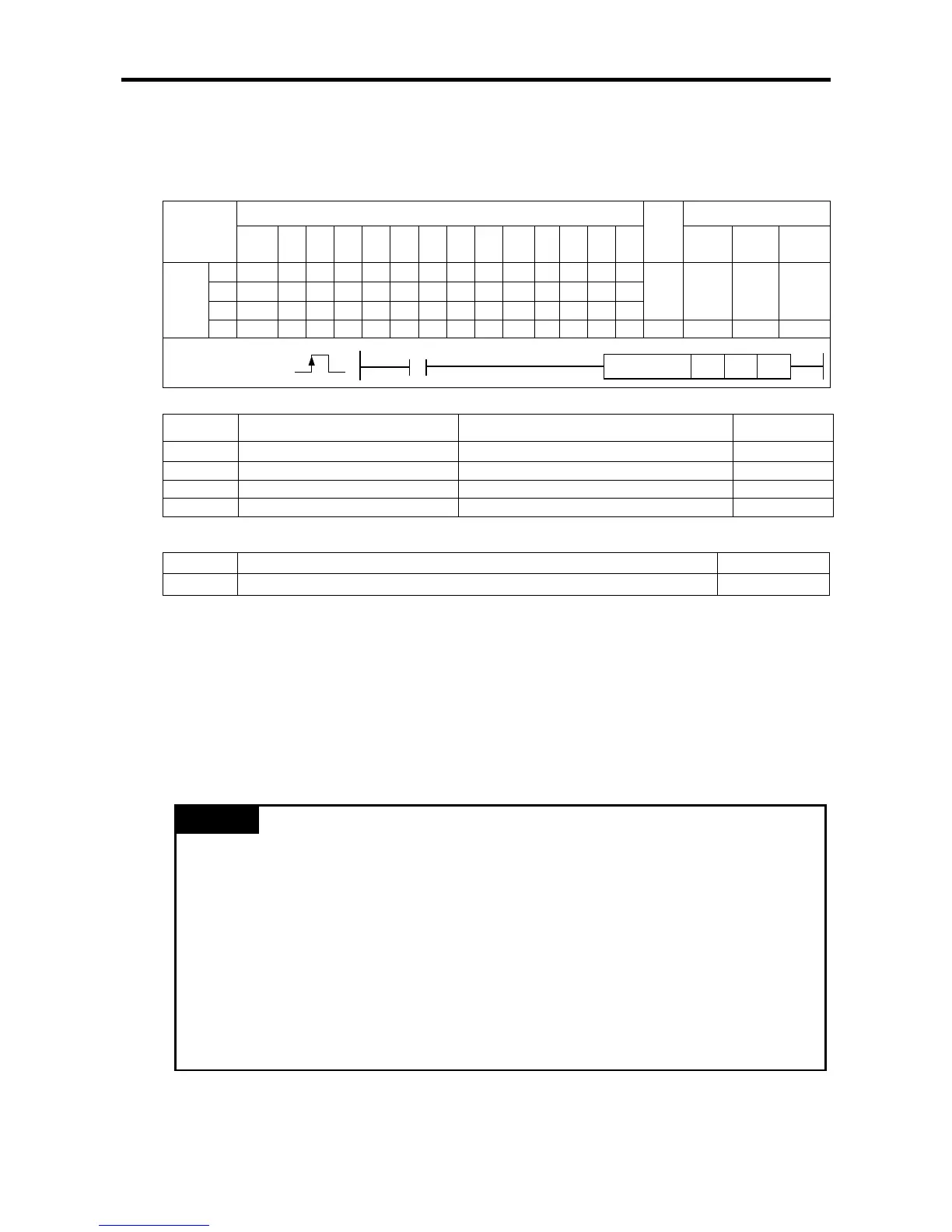
[Area Setting]
Operand
Data size
sl Slot No. of positioning module XGB is fixed at 0 WORD
[Flag Set]
Flag Description Device number
Error If the value of ax gets out of the range F110
(a) Function
• This instruction is for PWM output.
• While the input condition is On state, XGB postioning outputs pulse train in designated cycle time
in n1 and designated Off duty rate in n2 at designated axis in ax
• During PWM output, current address don’t change. Constant speed bit(X axis: K0420D, Y axis:
K0430S) and Operation bit(X axis: K04200 Y axis: K4300) set On.
(b) Error
• If the value designated as ax (instruction axis) is other than 0 and 1, the error flag (F110) is set
and the instruction is not executed.
Remark
• If PWM instruction is executed, other instruction do not operate. And upper/lower limit does not
work
• If PWM instruction is executed, STP, EMG instruction doesn’t operate. To stop output, Off the
Start-up contact
• If output cycle is changed, when operating APM_PWM, it cannot be applied.
• PWM applicable version
-XBM-DNxxS: H/W from V2.0, O/S V3.10
-XBC-DN/DPxxH: O/S from V2.03
-XEC-DN/DPxxH: O/S from V1.50
-XBC-DN/DPxxSU: O/S from V1.10
Instruction
Areas available
Step
Flag
PMK F L T C S Z D.x R.x
cons
tant
U N D R
Error
(F110)
Zero
(F111)
Carry
(F112)
WRT