Chapter 5 Positioning Instructions
5 - 29
5.2.11 Speed Synchronous Instruction
• The speed synchronous instruction (SSS instruction) is for speed synchronization at the set
synchronous speed rate and operation when the main axis is started with the axis set in the
instruction being the auxiliary axis. For details, refer to 3.1.8.
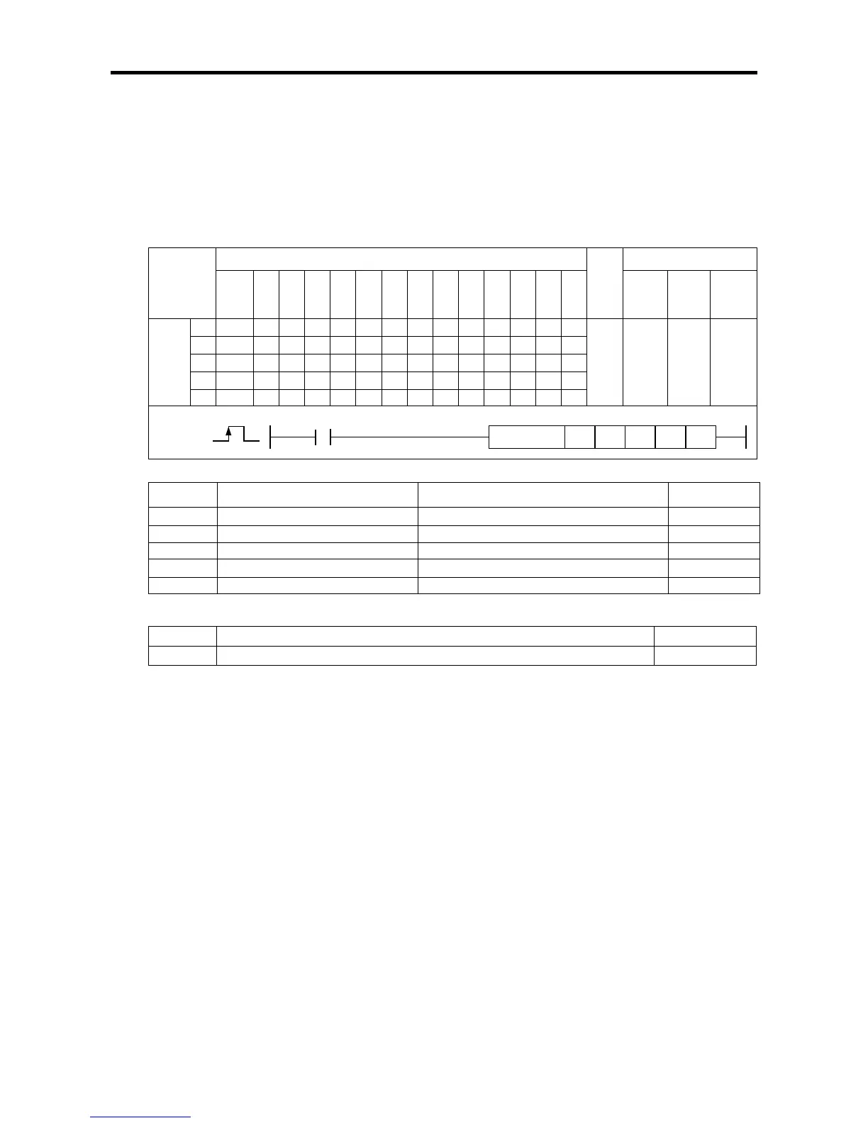
(1) Speed Synchronous Starting Instruction (SSS)
[Area Setting]
Operand
[Flag Set]
Flag Description Device number
Error If the value of ax gets out of the range F110
(a) Function
• This instruction is for executing the speed synchronous starting for synchronous starting.
• The axis set in the axis designated as ax at the rising edge of the input condition auxiliary axis, n3
becomes the main axis and the speed main axis position synchronous starting instruction is
executed.
• If the instruction is executed, the auxiliary axis stands by without generating actual pulse (the
operation status flag of the auxiliary axis (axis X:K4200, axis Y:K4300) turns On), and nn3 axis,
which is the main axis, it is started according to the speed synchronous ratio set in n1.
• The synchronous ratio settable in n1 is 0.01% ~ 100.00% (set value 1 ~ 10,000). If the set speed
ratio gets out of this range, error code 356 is issued.
• The delay time of n2 refers to the delay time it takes for speed of the auxiliary axis to reach the
current main axis speed. In XGB built-in positioning, when controlling the speed synchronization,
the speed of the current main axis is detected every 500 ㎲, and thereby the speed of the
auxiliary axis is adjusted. If the speed of the auxiliary axis is synchronized to the current main axis
speed without a delay time and immediately changed, there might be damage or shock noise to
the motor due to the sudden change of the auxiliary axis speed.
For example, assuming the speed ratio is 100.00% and the delay time is 5[ms], if the speed of the
main axis is 10,000[pps], the XGB built-in positioning adjusts the speed of the auxiliary axis
according to the speed of the main axis every 500[㎲] by adjusting the current speed for the
speed of the auxiliary axis to reach 10,000[pps].
The longer the delay time, the longer the delay time between the main axis and auxiliary axis, but
the output pulse is stably output. If there is likely to be step out of the motor, lengthen the delay
time.
Instruction
Areas available
Step
Flag
PMK F L T C S Z D.x R.x
con
stan