EasyManua.ls Logo

LSIS XEC-DP64H User Manual

LSIS XEC-DP64H
315 pages
To Next Page IconTo Next Page
To Previous Page IconTo Previous Page
Page #129 background imageLoading...
Page #129 background image
Chapter 5 Positioning Instructions
5 - 30
The delay time settable for n2 is 1 ~ 10[]. If it gets out of the settable range, error code 357 is
issued.
The main axis of n3 is settable between 0 and 9. If it gets out of the settable range, error code 355
is issued
Set
value
Main axis setting Remark
0
axis X
1
axis Y
2
High speed counter Ch0
3
High speed countCh1
4
High speed countCh2
5
High speed countCh3
6
High speed counter Ch4
Only the advanced type is
settable.
7
High speed counter Ch5
8
High speed counter Ch6
9
High speed counter Ch7
If you want to cancel the speed synchronous instruction after you execute it, execute the stop
instruction (STP) for the auxiliary axis.
The speed synchronous control is executable even when the origin is not fixed.
The speed synchronous control is synchronized to the speed of the main axis for operation of the
auxiliary axis, so even if the control method of the auxiliary axis is set as position control, starting
and stop are alternated by the operation of the main axis, with the rotation of the auxiliary axis
being in the same direction as the main axis.
If the M code of the auxiliary axis is On when you execute the speed synchronous instruction, error
code 353 is issued.
(b) Error
If the value designated as ax (instruction axis) is other than 0 and 1, the error flag (F110) is set
and the instruction is not executed.
(2) Example of Use of the Instruction
The speed synchronous starting instruction is described with the example of the following program.
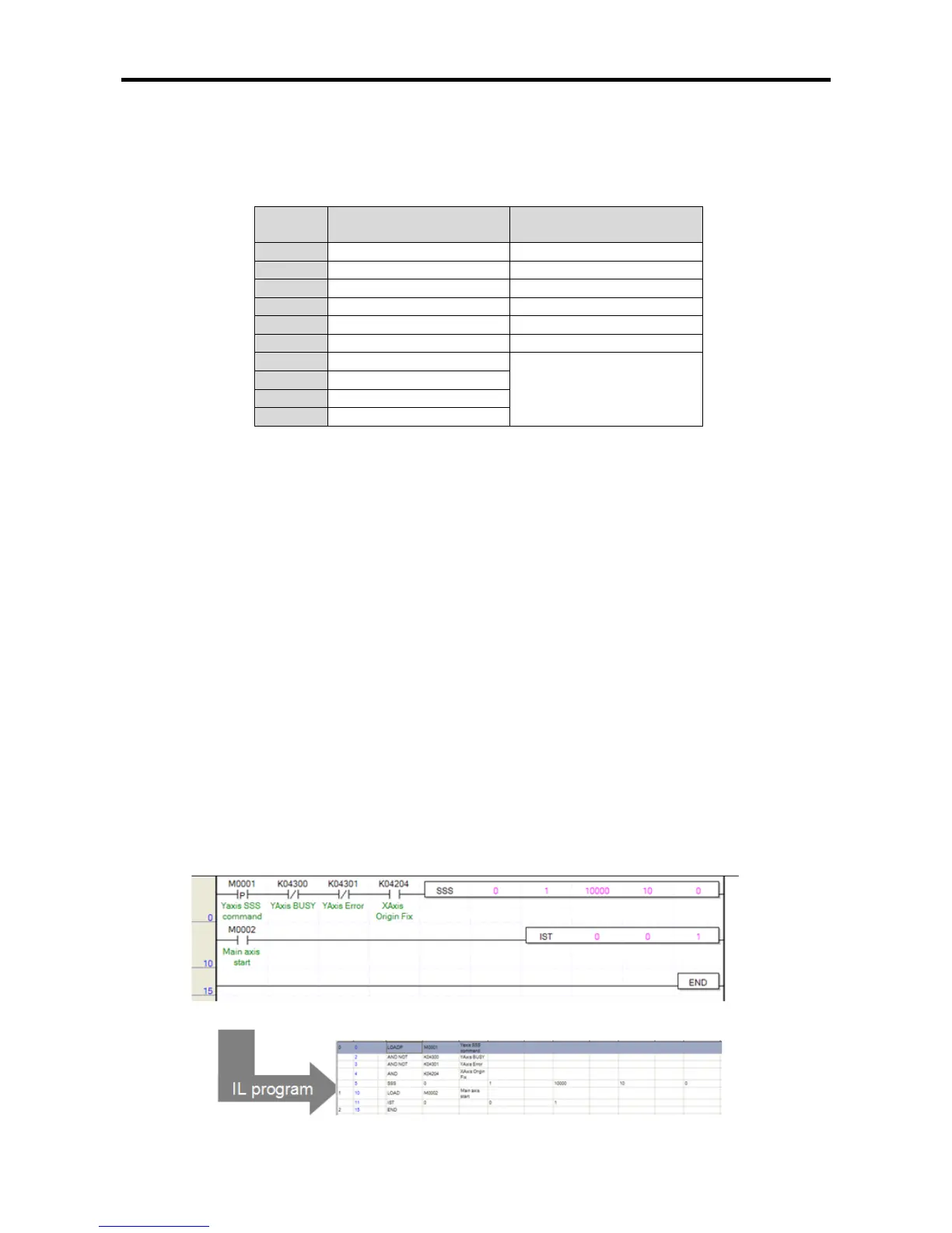
(a) Example of the Program
The following program example is about speed synchronous starting with the synchronization ratio
100.00[%] and the delay time being 10[] when the main axis is started if axis Y is the auxiliary
axis and axis X is the main axis.

Table of Contents

Questions and Answers:

LSIS XEC-DP64H Specifications

General IconGeneral
BrandLSIS
ModelXEC-DP64H
CategoryController
LanguageEnglish

Summary

XGB Built-in Positioning

Safety Instruction

Crucial safety guidelines to be followed before operating the product.

Chapter 1 General

Provides general information about the positioning function, including purpose and features.

Chapter 2 General Specification

Provides general specifications for the XGB series, including environmental and immunity details.

Chapter 3 Before Positioning

Explains various positioning functions, parameters, and operation data.

Chapter 4 Positioning Check

Outlines the procedure for testing XGB positioning operation before use.

Chapter 5 Positioning Instructions

Provides detailed explanations for various positioning instructions like Origin Return, Direct Start, etc.

Chapter 6 Positioning Monitoring Package

Introduces the XGB positioning monitoring package for status monitoring and test operation.

Chapter 7 Program Examples of Positioning

Provides practical program examples for various positioning functions.

Chapter 8 Troubleshooting Procedure

Outlines basic steps for troubleshooting errors in XGB PLC and positioning functions.

Appendix 1 List of Error Codes

Details specific error codes related to the XGB positioning function.

Appendix 2 Positioning Instruction and K area List

Provides a list of dedicated K areas for positioning parameters and instructions.

Appendix 3 Motor Wiring Example

Illustrates wiring examples for connecting XGB PLC to servo motors.

Appendix 4 Dimension

Provides dimensional drawings for standard XGB main units (XBM-DN/DR series).

Related product manuals