EasyManua.ls Logo

LSIS XEC-DP64H User Manual

LSIS XEC-DP64H
315 pages
To Next Page IconTo Next Page
To Previous Page IconTo Previous Page
Page #127 background imageLoading...
Page #127 background image
Chapter 5 Positioning Instructions
5 - 28
(c) Operation of the Program
The SSP instruction is executed if there is the rising edge of M0001, which was used as the main
axis position synchronous instruction signal.
Since the second operand is 1 (axis Y), axis Y is the auxiliary axis, and as the fifth operand is
0(axis X), so the main axis is axis X.
No.1 step of axis X is indirectly started if there is the rising edge of M0002, which is the indirect
starting instruction signal of the main axis.
When the current position of the main axis during operation becomes 10,000[Pulse], set in the third
operand of the SSP instruction, axis Y, which is the auxiliary axis, starts No. 1 step, which is the
operation step set in the fourth operand of the SSP instruction.
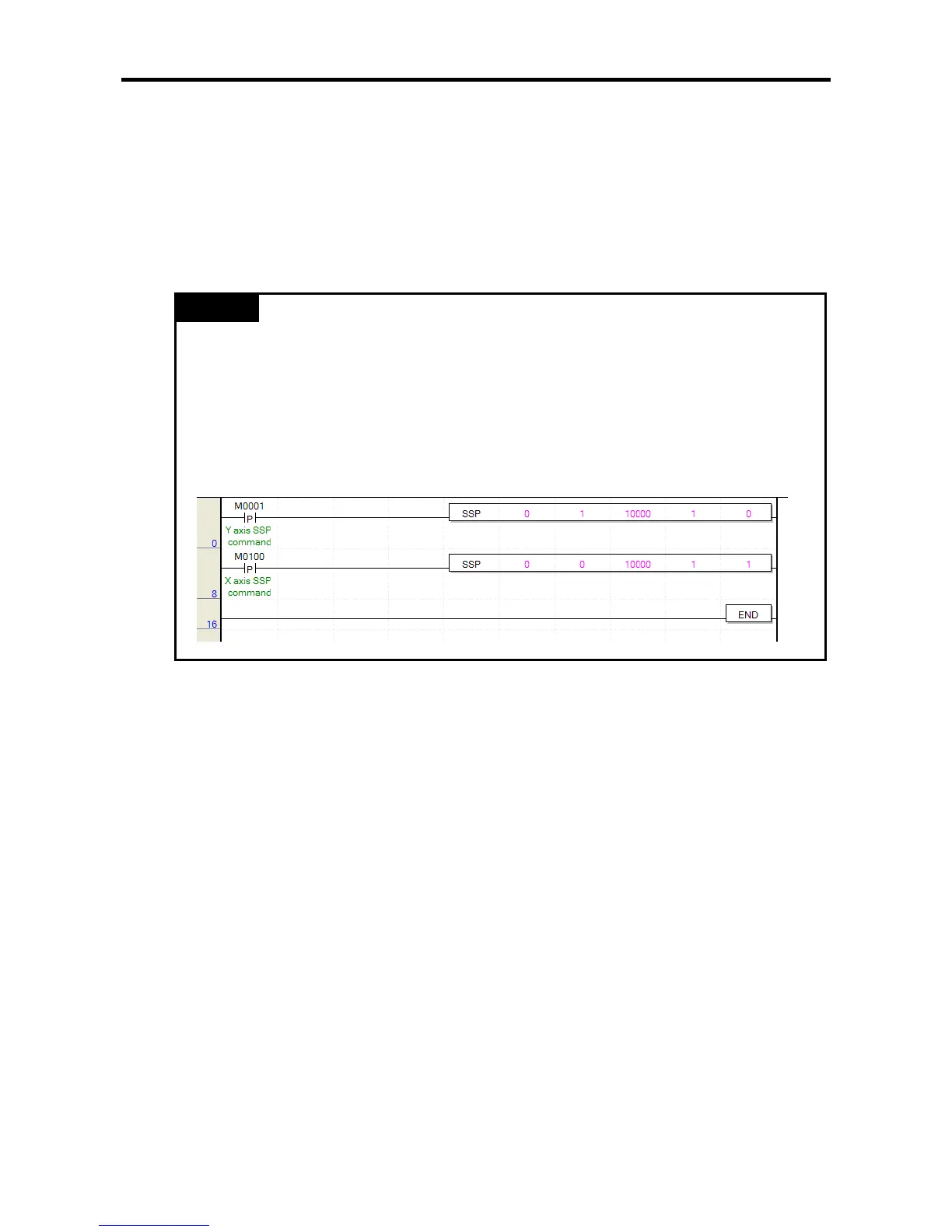
Remark
When you use the main axis position synchronous instruction, if the axis set as the main axis
has already been started as the main axis position synchronous auxiliary axis, error code 349 is
issued and it is not executed. If the following example, axis Y becomes the auxiliary axis and
axis X becomes the main axis at the rising edge of M0001 and the main axis position
synchronous instruction is executed. If there is the rising edge of M0100, the position
synchronous instruction is issued with axis X being the auxiliary axis and axis Y being the main
axis. In this case, since axis Y used as the main axis, is already being started as the auxiliary
axis of the main axis position synchronous instruction, axis X generates error code 349 and is
not started.

Table of Contents

Questions and Answers:

LSIS XEC-DP64H Specifications

General IconGeneral
BrandLSIS
ModelXEC-DP64H
CategoryController
LanguageEnglish

Summary

XGB Built-in Positioning

Safety Instruction

Crucial safety guidelines to be followed before operating the product.

Chapter 1 General

Provides general information about the positioning function, including purpose and features.

Chapter 2 General Specification

Provides general specifications for the XGB series, including environmental and immunity details.

Chapter 3 Before Positioning

Explains various positioning functions, parameters, and operation data.

Chapter 4 Positioning Check

Outlines the procedure for testing XGB positioning operation before use.

Chapter 5 Positioning Instructions

Provides detailed explanations for various positioning instructions like Origin Return, Direct Start, etc.

Chapter 6 Positioning Monitoring Package

Introduces the XGB positioning monitoring package for status monitoring and test operation.

Chapter 7 Program Examples of Positioning

Provides practical program examples for various positioning functions.

Chapter 8 Troubleshooting Procedure

Outlines basic steps for troubleshooting errors in XGB PLC and positioning functions.

Appendix 1 List of Error Codes

Details specific error codes related to the XGB positioning function.

Appendix 2 Positioning Instruction and K area List

Provides a list of dedicated K areas for positioning parameters and instructions.

Appendix 3 Motor Wiring Example

Illustrates wiring examples for connecting XGB PLC to servo motors.

Appendix 4 Dimension

Provides dimensional drawings for standard XGB main units (XBM-DN/DR series).

Related product manuals