EasyManua.ls Logo

LSIS XEC-DP64H User Manual

LSIS XEC-DP64H
315 pages
To Next Page IconTo Next Page
To Previous Page IconTo Previous Page
Page #177 background imageLoading...
Page #177 background image
Chapter 5 Positioning Instructions
5 - 78
•The range of the main axis setting of MST_AXIS is 0 ~ 9 as shown below. If this range is exceeded,
error code 355 is generated.
•To cancel the execution of speed synchronization instruction, run the stop instruction (APM_STP)
for the sub-axis.
•Speed synchronization control can be executed even when the Origin of the sub-axis has not be
determined.
•In speed synchronization, the sub-axis is synchronized to the main axis. Therefore, even if the
control mode of the sub-axis is set up position control, it repeats start and stop according to the
operation of the main axis, and the direction of rotation of the sub-axis is the same as that of the
main axis.
•If the M code of the sub-axis is ON at the execution of the speed synchronization instruction, error
code 353 is outputted to STAT.
(2) Sample Instruction
•The program below is to show exemplary operation of speed synchronization start instruction.
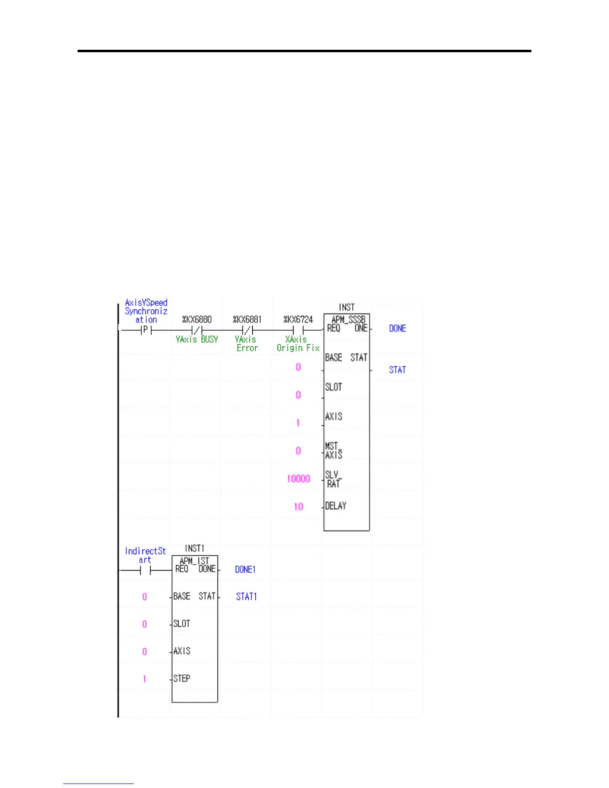
(a) Sample Program
•In the sample program below with the Y-axis as the sub-axis and the X-axis as the main axis, the
speed synchronization start-up is executed at the synchronization ratio of
100.00[%] and delay time of 10[] when the main axis is started-up.

Table of Contents

Questions and Answers:

LSIS XEC-DP64H Specifications

General IconGeneral
BrandLSIS
ModelXEC-DP64H
CategoryController
LanguageEnglish

Summary

XGB Built-in Positioning

Safety Instruction

Crucial safety guidelines to be followed before operating the product.

Chapter 1 General

Provides general information about the positioning function, including purpose and features.

Chapter 2 General Specification

Provides general specifications for the XGB series, including environmental and immunity details.

Chapter 3 Before Positioning

Explains various positioning functions, parameters, and operation data.

Chapter 4 Positioning Check

Outlines the procedure for testing XGB positioning operation before use.

Chapter 5 Positioning Instructions

Provides detailed explanations for various positioning instructions like Origin Return, Direct Start, etc.

Chapter 6 Positioning Monitoring Package

Introduces the XGB positioning monitoring package for status monitoring and test operation.

Chapter 7 Program Examples of Positioning

Provides practical program examples for various positioning functions.

Chapter 8 Troubleshooting Procedure

Outlines basic steps for troubleshooting errors in XGB PLC and positioning functions.

Appendix 1 List of Error Codes

Details specific error codes related to the XGB positioning function.

Appendix 2 Positioning Instruction and K area List

Provides a list of dedicated K areas for positioning parameters and instructions.

Appendix 3 Motor Wiring Example

Illustrates wiring examples for connecting XGB PLC to servo motors.

Appendix 4 Dimension

Provides dimensional drawings for standard XGB main units (XBM-DN/DR series).

Related product manuals