EasyManua.ls Logo

LSIS XEC-DP64H User Manual

LSIS XEC-DP64H
315 pages
To Next Page IconTo Next Page
To Previous Page IconTo Previous Page
Page #134 background imageLoading...
Page #134 background image
Chapter 5 Positioning Instructions
5 - 35
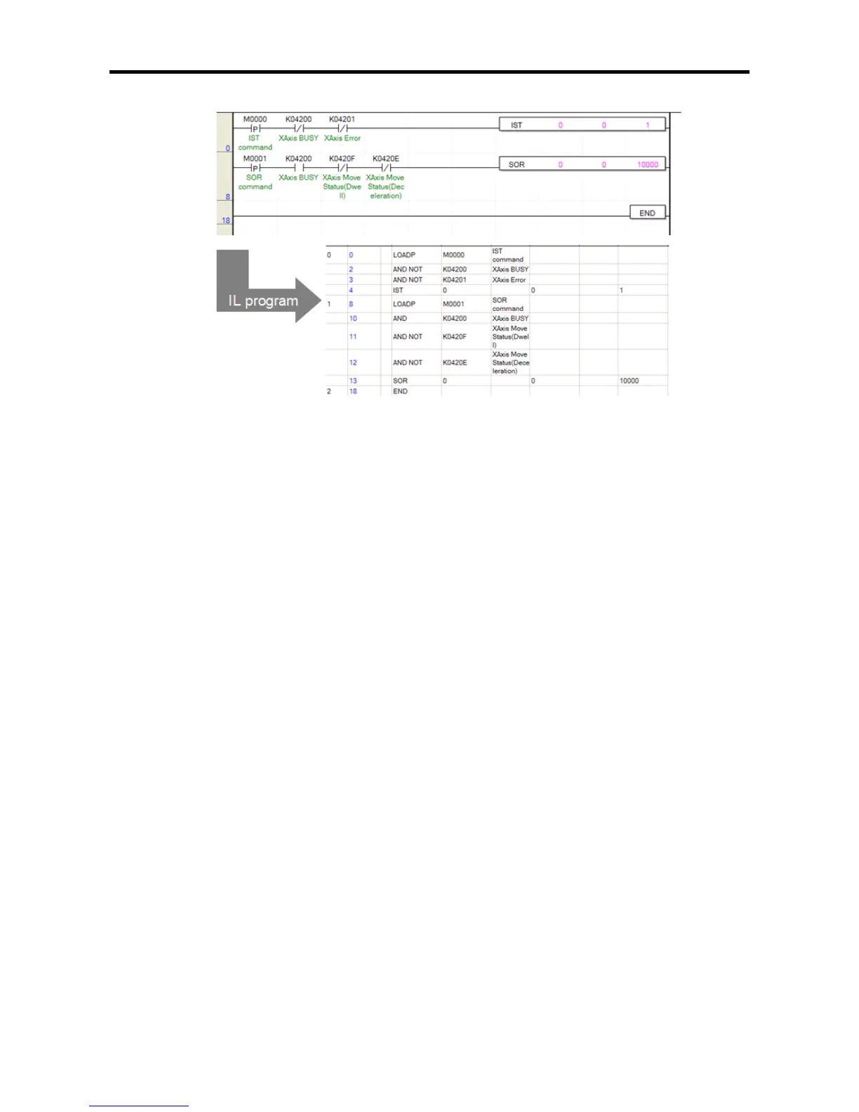
(a) Example of the Program
(b) Operation of the Program
The positioning axis X is indirectly started with operation step 1 if there is the rising edge of M0000
used as the indirect starting instruction signal.
If there is the rising edge of M0001 used as the instruction signal of the speed override instruction
during operation, operation continues by changing the speed of the currently operating step into
10,000[pps]. (Note that the value of the operation speed of No. 1 step set in the positioning
parameter is not changed)
• If the speed override instruction is executed during deceleration or dwell, error code 377 is issued.
To prevent this, make the program by connecting the axis X dwell flag to the starting contact point
with the normally closed contact point (contact point B).

Table of Contents

Questions and Answers:

LSIS XEC-DP64H Specifications

General IconGeneral
BrandLSIS
ModelXEC-DP64H
CategoryController
LanguageEnglish

Summary

XGB Built-in Positioning

Safety Instruction

Crucial safety guidelines to be followed before operating the product.

Chapter 1 General

Provides general information about the positioning function, including purpose and features.

Chapter 2 General Specification

Provides general specifications for the XGB series, including environmental and immunity details.

Chapter 3 Before Positioning

Explains various positioning functions, parameters, and operation data.

Chapter 4 Positioning Check

Outlines the procedure for testing XGB positioning operation before use.

Chapter 5 Positioning Instructions

Provides detailed explanations for various positioning instructions like Origin Return, Direct Start, etc.

Chapter 6 Positioning Monitoring Package

Introduces the XGB positioning monitoring package for status monitoring and test operation.

Chapter 7 Program Examples of Positioning

Provides practical program examples for various positioning functions.

Chapter 8 Troubleshooting Procedure

Outlines basic steps for troubleshooting errors in XGB PLC and positioning functions.

Appendix 1 List of Error Codes

Details specific error codes related to the XGB positioning function.

Appendix 2 Positioning Instruction and K area List

Provides a list of dedicated K areas for positioning parameters and instructions.

Appendix 3 Motor Wiring Example

Illustrates wiring examples for connecting XGB PLC to servo motors.

Appendix 4 Dimension

Provides dimensional drawings for standard XGB main units (XBM-DN/DR series).

Related product manuals