EasyManua.ls Logo

LSIS XEC-DP64H User Manual

LSIS XEC-DP64H
315 pages
To Next Page IconTo Next Page
To Previous Page IconTo Previous Page
Page #124 background imageLoading...
Page #124 background image
Chapter 5 Positioning Instructions
5 - 25
(2) Example of Use of the Instruction
The deceleration stop instruction is described with the example of the following program.
(a) Example of the Program
(b) Device Used
Device
Description
Data size
Example of setting
M0000
origin return instruction
signal
BIT -
M0001
Indirect starting instruction
signal
BIT -
M0002
Deceleration stop
instruction signal
BIT -
K4200
signal during axis X
position control
BIT -
K4201 axis X error BIT -
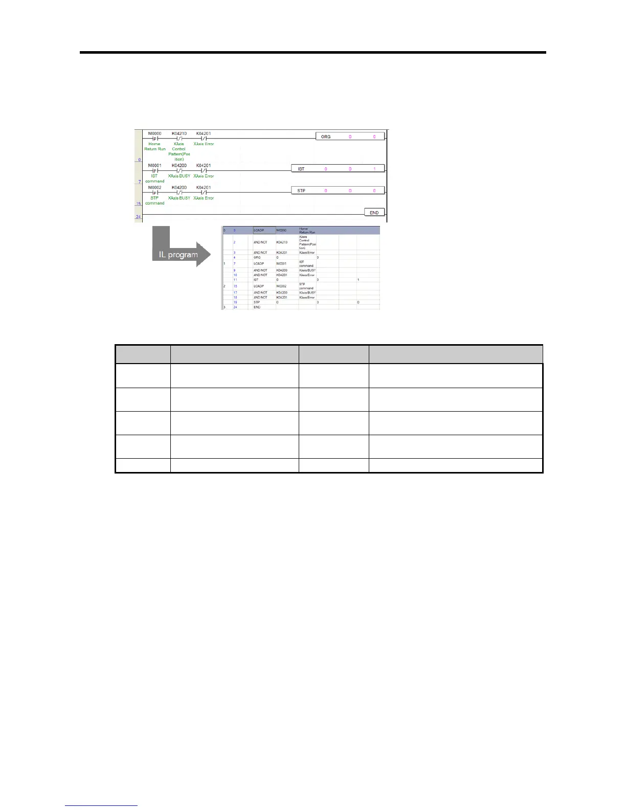
(c) Operation of the Program
• IST instruction is executed when there is the rising edge of M0001, which was used as the indirect
starting instruction signal.
- In the program above, the indirect starting of No. 1 step of axis X is executed.
If there is the rising edge of M0002, which is the deceleration stop instruction signal during
operation, the deceleration stop instruction is executed according to the setting of STP instruction.
- Since sl (first Operand) and ax(second Operand) are set at 0, the deceleration stop is executed
for axis X of basic unit built-in positioning.
- Since the deceleration time is set at 0, if the STP instruction is executed, it stops right away
without deceleration.
Note the following in executing the STP instruction.
- If it has been stopped by the deceleration stop instruction, because the positioning operation has
not been finished to the set target position, no positioning completion signal (axis X:K4202, axis
Y:K4302) is generated, and if M code is set, the M code signal does not turn On either.
- In this case, the operation step number maintains the current step.
- If the indirect starting instruction is executed again afterwards, the operation methods differs
according to the coordinates type.
1) Absolute coordinates: The remaining position output which has not been output from the
current operation step is output.
2) Incremental coordinates: Operation is conducted as much as the new target position.
- For example, if the target value of the corresponding step is 20,000 and it has been stopped at
15,000 by the deceleration stop instruction, and if the indirect starting is executed again, in case
of absolute coordinates, operation is done as much as 5,000 and stops at 20,000, and in case of
Incremental coordinates, it newly moves 20,000 and stops at 35,000.

Table of Contents

Questions and Answers:

LSIS XEC-DP64H Specifications

General IconGeneral
BrandLSIS
ModelXEC-DP64H
CategoryController
LanguageEnglish

Summary

XGB Built-in Positioning

Safety Instruction

Crucial safety guidelines to be followed before operating the product.

Chapter 1 General

Provides general information about the positioning function, including purpose and features.

Chapter 2 General Specification

Provides general specifications for the XGB series, including environmental and immunity details.

Chapter 3 Before Positioning

Explains various positioning functions, parameters, and operation data.

Chapter 4 Positioning Check

Outlines the procedure for testing XGB positioning operation before use.

Chapter 5 Positioning Instructions

Provides detailed explanations for various positioning instructions like Origin Return, Direct Start, etc.

Chapter 6 Positioning Monitoring Package

Introduces the XGB positioning monitoring package for status monitoring and test operation.

Chapter 7 Program Examples of Positioning

Provides practical program examples for various positioning functions.

Chapter 8 Troubleshooting Procedure

Outlines basic steps for troubleshooting errors in XGB PLC and positioning functions.

Appendix 1 List of Error Codes

Details specific error codes related to the XGB positioning function.

Appendix 2 Positioning Instruction and K area List

Provides a list of dedicated K areas for positioning parameters and instructions.

Appendix 3 Motor Wiring Example

Illustrates wiring examples for connecting XGB PLC to servo motors.

Appendix 4 Dimension

Provides dimensional drawings for standard XGB main units (XBM-DN/DR series).

Related product manuals