363-206-305 Detailed Level Procedure:
DLP-514
Issue 3, June 2000 Page 19 of 22
DDM-2000 F
IBER
R
EACH
W
IDEBAND
S
HELF
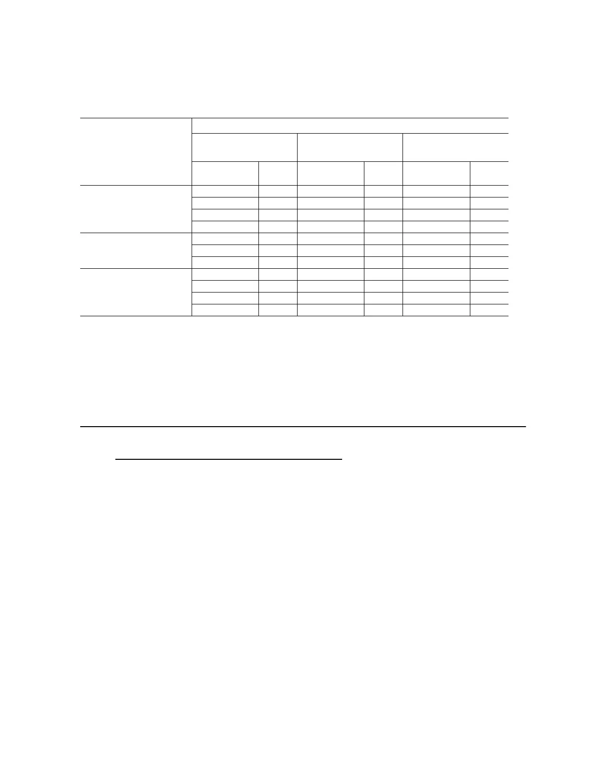
Table M – DDM-2000 FiberReach Operating at an OC-12 Rate to WaveStar 2.5G/10G
Measured Optical Power and Required LBO
Notes
1. Measured power is defined to be the measured power of the light emitted from receive fiber con-
nector at OLIU.
2. The minimum measured received power allows for optical path penalty and unallocated margin.
Connector loss is not allotted for; it should already be accounted for in the optical power measure-
ment.
3. The margin for falling within the maximum rx power is 1.0 dB.
Fiber Connection
10. At far end, connect the input optical fiber to the proper
OLIU IN
(receive)
connector.
11. Did
FAULT
LED go off on the far-end
OLIU
?
If
NO
, continue with
Step 12
.
If
YES
, proceed to
Step 13
.
12. Check optical fiber connections. Verify integrity of fiber connections by
ensuring correct output at one end is connected to correct input at the other
end. Replace
OLIU
with flashing LED. Continue with this procedure when
trouble is cleared.
13. At near end, connect the input optical fiber(s) to the corresponding
OLIU
IN
(receive) connector.
Receiver
LEY13 OC12/STM4
(WaveStar)
LEY14 OC12/STM4
(WaveStar) 29G-U/29H-U OLIU
Transmitter
Received
Power (dBm)
LBO
(dB)
Received
Power (dBm)
LBO
(dB)
Received
Power (dBm)
LBO
(dB)
LEY13 OC12/STM4
(WaveStar)
-7.0 to -34.0 0
LEY14 OC12/STM4
(WaveStar)
-14.0 to -15.0 5
-15.0 to -34.0 0
29G-U/29H-U OLIU
0.0 to -5.0 15
-5.0 to -10.0 10 0.0 to -3.0 10
-10.0 to -15.0 5 -3.0 to -8.0 5
-15.0 to -29.5 0 -8.0 to -28.0 0