363-206-305
Administration and Provisioning
8-28
Issue 3 June 2000
Pass-Through Cross-Connection
8
Another type of cross-connection allows a high-speed VT1.5 or STS-1 channel to
be "passed-through" between two high-speed ring interfaces. This is used in all
path-switched ring applications at nodes where traffic is not dropped. The high-
speed time slot entering must be the same leaving in this type of cross-
connection. In path switched rings, pass-through grooming (passing a signal on a
ring time slot that is different from the ring time slot on which it was received) is not
supported.
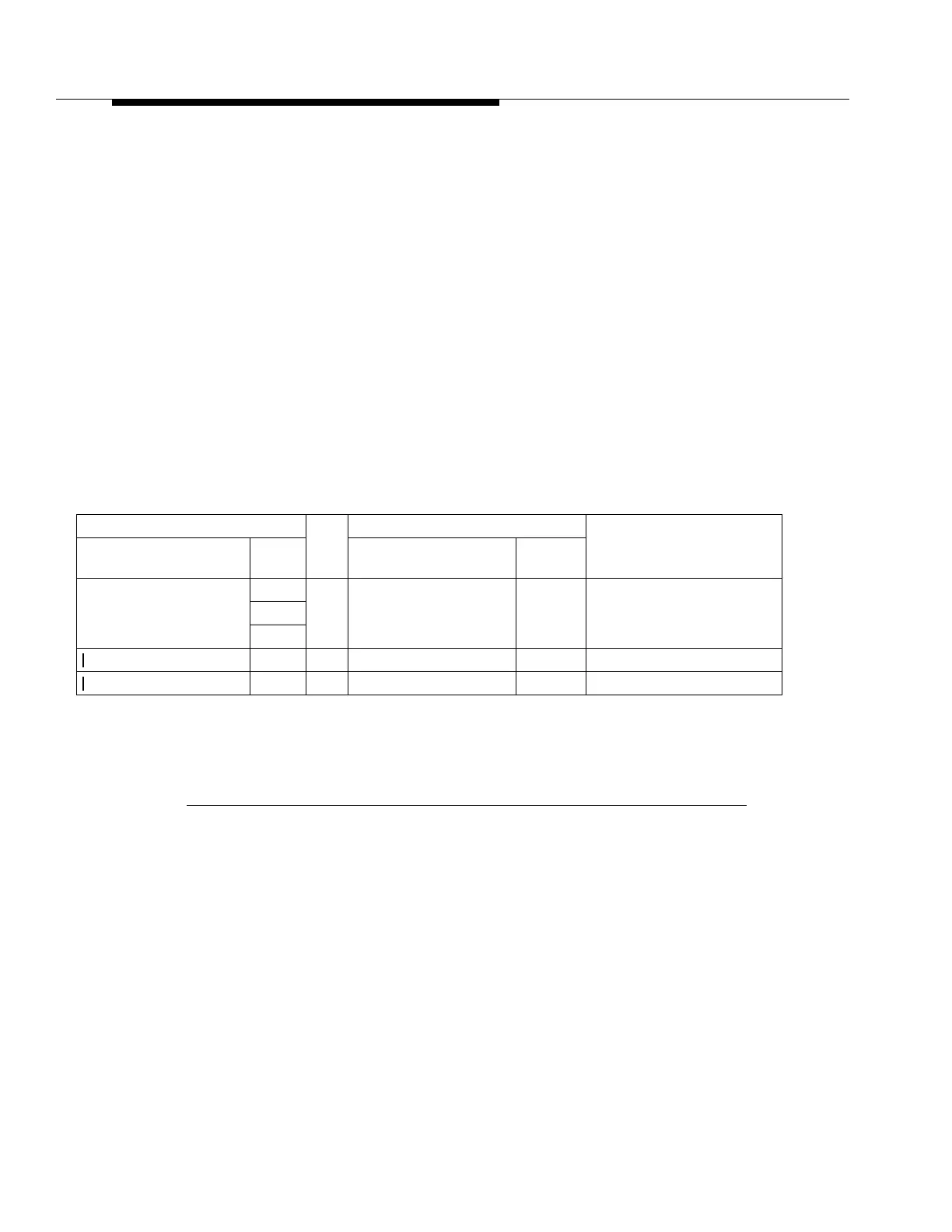
As shown in Table 8-9, pass through cross-connections are designated by using
the same VT ring channel twice in the cross-connect address. For example, the
single command
ent-crs-vt1:m-1-5-3:m-1-5-3
connects a pass through
cross-connection both to and from the third VT1.5 within the fifth VT group within
the first STS-1 of both the service and protection ring.
Depending on local practice, work orders will normally identify the low-speed port
designations at the entry and exit points in the network and the target identifiers
(TIDs) of the NEs at these points. The work order may also designate the VT1.5
ring channel which will be used for this service. If the work order does not
designate a ring channel to use, use the command
rtrv-crs-vt1;
to identify all
the ring channels that are currently unassigned. The work order also may not
designate all the other NEs on the ring that need to be provisioned with pass
through cross-connections. In this case, use successive
rtrv-map-nei
commands to identify the TIDs for all the NEs in a ring.
Table 8-9. DDM-2000 FiberReach Manual VT1.5 Cross Connections (Pass-
Through) 1 X 1 and 1 X 7 Configurations
From To
Example
CommandsAddress OLIU Address
CP Type
(Notes)
m-1-{1-7,all}-{1-4,all} OC-1 <--> m-1-{1-7,all}-{1-4,all} OC-1 ent-crs-vt1:m-1-1-2,m-1-1-2
ent-crs-vt1:m-1-3-4,m-1-3-4
m-{1-3}{1-7,all}-{1-4,all} OC-3 <--> m-{1-3}{1-7,all}-{1-4,all} OC-3 ent-crs-vt1:m-1-2-4,m-1-2-4
m-{1-12}{1-7,all}-{1-4,all} OC-12 <--> m-{1-12}{1-7,all}-{1-4,all} OC-12 ent-crs-vt1:m-1-2-4,m-1-2-4
Notes
1.
Pass Through Signals
: Address on the left side
must be
identical to the
address on the right side. There is no interchange function for "pass through"
signals.