363-206-305
Circuit Pack Descriptions
7-8
Issue 3 June 2000
Power Circuitry
7
The SYSCTL receives two sources of
−
48 volts which are diode ORed, fused, and
filtered prior to conversion to a +5 volt source to power the rest of the circuit pack.
A failure of the fuse or converter causes the red FAULT LED to light.
BBG8/BBG8B SYSCTL Hardware Setting
7
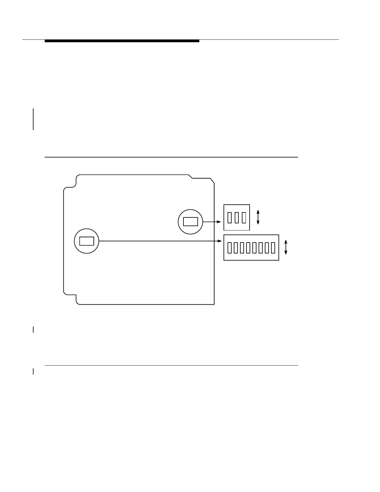
The BBG8/BBG8B circuit pack has two hardware switches. Switch 1 (S1) is for
product identification and Switch 2 (S2) for the DDM-2000 FiberReach DCC
channel. See Figure 7-3.
Note
: The switch is set by moving the slide toward the desired position. For DDM-
2000 FiberReach, all three S1 switches should be in the OFF position. All S2
switches should be ON, with the exception of Switch S2-2, which should be set to
OFF.
Figure 7-3. BBG8/BBG8B SYSCTL Option Switches
S1
12
ON
OFF
ON
S1
Edge
Connector
Component Side
S2
12345678
ON
OFF
ON
S2
3