363-206-305
Circuit Pack Descriptions
7-32
Issue 3 June 2000
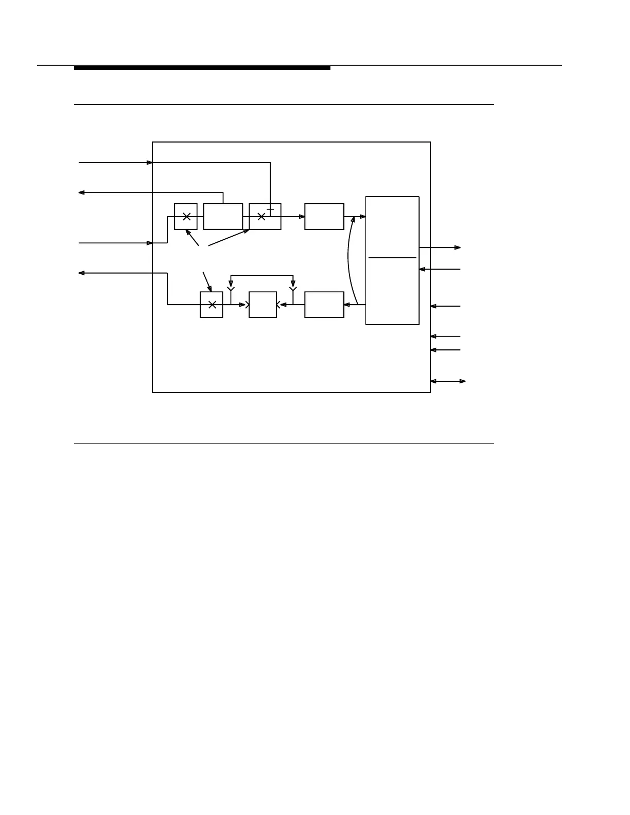
Figure 7-14. BBG4/BBG4B DS3 Circuit Pack Block Diagram
VMR Function
7
Before the DS3 signal is B3ZS-encoded (receive) or decoded (transmit), a VMR
function can be provisioned via the control circuitry for one of three possible
modes. These three modes are as follows:
■
VMR with DS3 AIS insertion—default
■
VM without removal of violations but with AIS insertion
■
No violation monitoring CC mode with options for
—AIS insertion
— No AIS insertion.
DS3
Receiver
Hybrid
Protection
Relays
Multiplexer
Demultiplexer
DS3
Driver
LBO
Intrashelf
STS-1
To/From
OLIU CPs
From
From
Shelf
-48V Fuses
SYSCTL
-48V A
-48V B
Timing
Control
To/From
Loopback
To/From
Companion CP
To/From
DS3
(Service &
Protection)
TGS CPs
(Service &
Protection)
DSX-3