363-206-305
Circuit Pack Descriptions
Issue 3 June 2000
7-57
Due to the increased power needs of the BBF8, only three BBF8 circuit packs
(including protection) may be used in a function group. Powering for these packs is
provided by the 28-type in the FiberReach shelf. Pack mixing with Quad DS1/T1
EXT circuit packs is not recommended. The HDSL interfaces do not support line
powering. The BBF8 is compatible with DDM-2000 FiberReach Release 2.2 and
later.
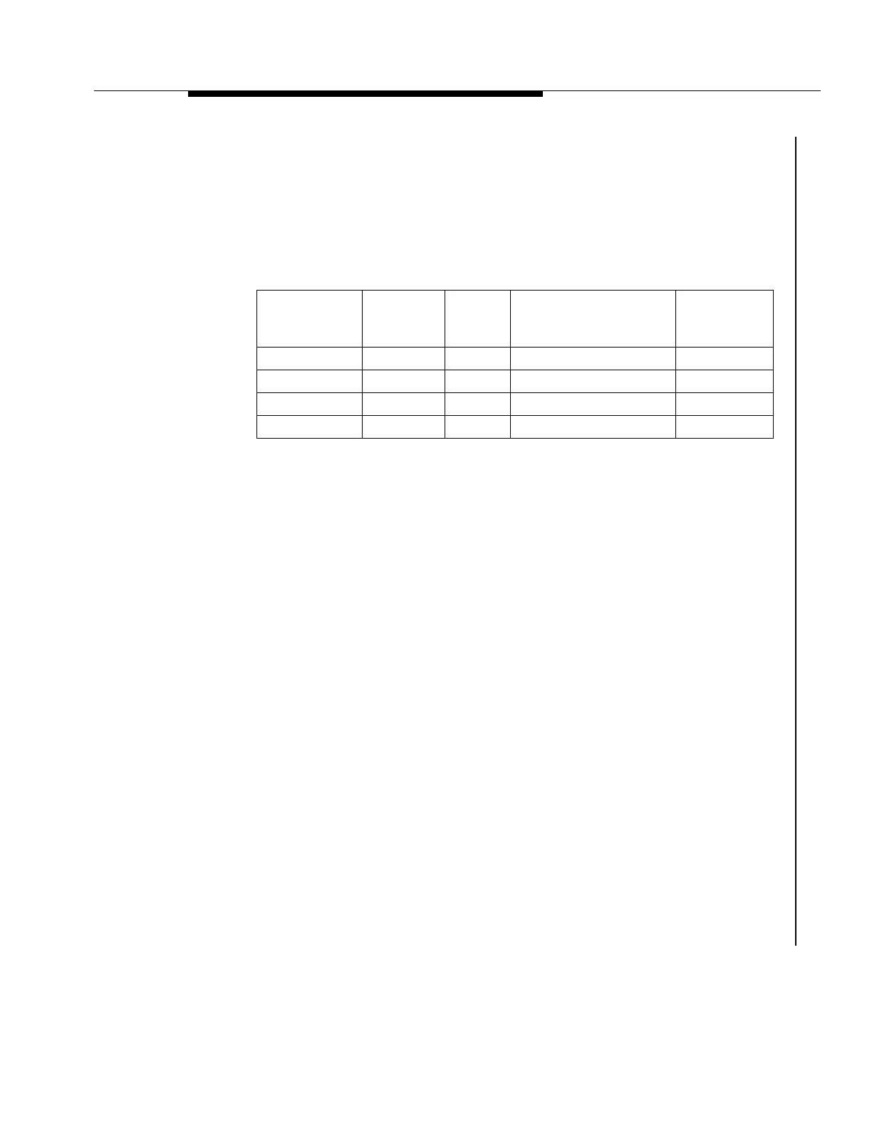
Table 7-7. HDSL Line Specifications
Control Circuitry
7
The HDSL circuit pack interfaces with the SYSCTL over the intra-shelf control bus.
Redundancy in the intra-shelf control bus assures the level of control required to
perform protection switching and alarming of a faulty circuit pack. The HDSL
provides maintenance elements for reporting the status of the circuit pack and the
incoming VT1.5 and HDSL signals, as well as the circuit pack inventory
information (
CLEI
code, date of manufacture, etc.). These maintenance elements
are used by the SYSCTL for fault detection and isolation. Conversely, the HDSL
responds to control signals from the SYSCTL (such as FAULT LED control). The
PM processor collects information from the framing circuitry and generates DS1
PM parameters which are stored in the HDSL pack. Access to the PM information
is via a faceplate-mounted connector. Each connector supports two RS-232
interfaces (one for each HDSL port). The port is accessed by using a cable
supplied with the circuit pack.
Protection Circuitry
7
Optional 1xN revertive HDSL circuit pack protection is provided, and this
protection is independent of the 28-type circuit pack. The HDSL protection switch
points are implemented with on-board relays on the HDSL side and with logic
selectors at the VT-G level on the active and standby 28-type circuit packs. The
SYSCTL controls these relays through two serial interfaces so that a failure of one
serial interface to the HDSL does not prevent control of the relays. If +5V power on
the HDSL fails, the relays default to the protection state.
Shorting contacts are provided in the HDSL backplane connector so that when
the circuit pack is removed, the HDSL cable pairs short through to the protection
bus.
Cable Gauge
Loss at
196 kHz
dB/ft.
Ohms
per
kft
Maximum Loop
for 35 dB Loss
Ohms at
Maximum
Length
26/0.40 mm 3.880 83.3 9.0 kft/2.75 km/1.7 mi 750
24/0.51 mm 2.841 51.9 12.3 kft/3.75 km/2.3 mi 638
22/0.61 mm 2.177 32.4 16.1 kft/4.9 km/3.0 mi 520
19/0.91 mm 1.535 16.1 22.8 kft/6.95 km/4.3 mi 367