363-206-305
Administration and Provisioning
Issue 3 June 2000
8-39
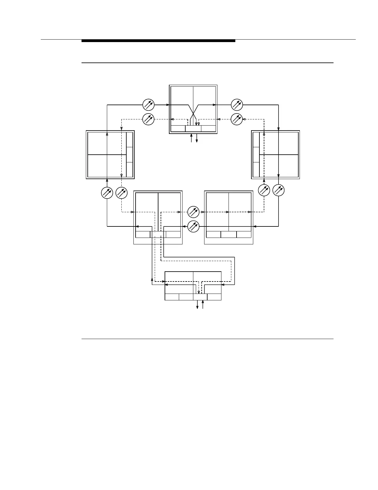
Figure 8-2. Example Single-Homed Path-Switched Ring Configuration Cross-
Connections
In Figure 8-2, the DDM-2000 OC-3 shelf at RT3 supports a single-homed OC-1
interface in function unit B. Signals are connected between the OC-3 interface in
Main-1 and the OC-1 interface(s) in FN-B-1, and between the OC-3 interface in
Main-2 and the OC-1 interface(s) in FN-B-2. Switching is not done on the DDM-
2000 OC-3 Multiplexer on these interfaces; rather VT1.5 level path switching is
done on the DDM-2000 FiberReach Multiplexer and on the DDM-2000 OC-3 shelf
at the CO node. This allows DDM-2000 FiberReach nodes to interface with DDM-
OLIU
IN
OUT
OLIU
IN
OUT
Ring 2
Ring 1
OLIU
IN
OUT
OLIU
IN
OUT
OLIU
IN
OUT
OLIU
IN
OUT
OLIU
IN
OUT
OLIU
IN
OUT
Ring 1
MAIN 1MAIN 2
MAIN 1MAIN 2
MAIN 1 MAIN 2 MAIN 1 MAIN 2
FIBERREACH
RT4RT3
OC-3 RING
Ring 2
Ring 1
Ring 2
MAIN 1 MAIN 2
DS1s
RT1
OLIU
IN
OUT
OLIU
IN
OUT
MAIN 2 MAIN 1
RT2
CO
DS1s
OC-1
OC-1
OC-1 RING
LS-A
LS-B
LS-C LS-D
FN-A
FN-B
FN-C
FN-A
FN-B
FN-C
FN-A
FN-B
FN-C
FN-A
FN-B
FN-C FN-A
FN-B
FN-C