363-206-305
Shelf Descriptions and Configurations
3-22
Issue 3 June 2000
Figure 3-21. DDM-2000 FiberReach with Unprotected T1 Extension Services
T1 Extensions and DS1 Service
3
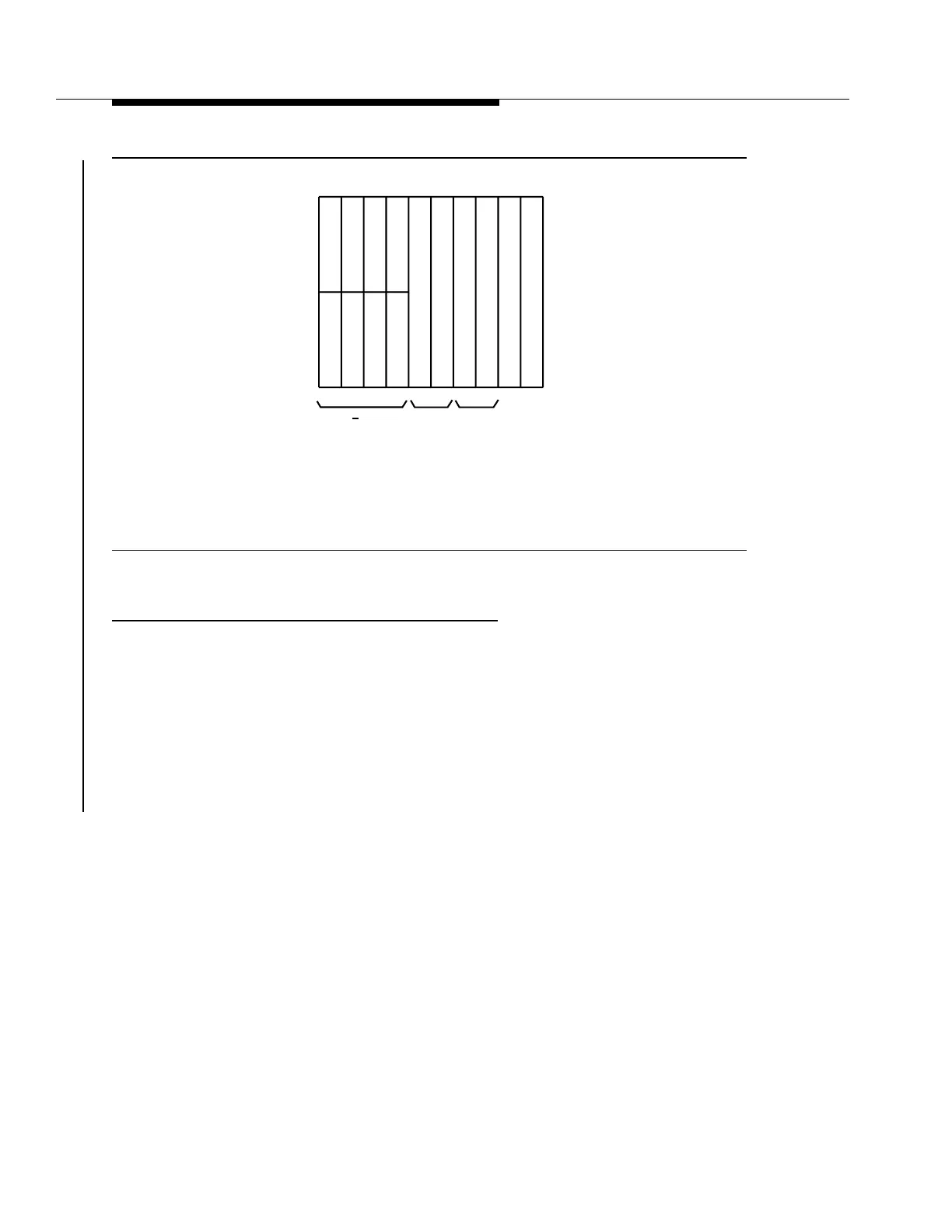
Figure 3-22 shows an example of the DDM-2000 FiberReach in a combination
configuration of T1 extensions and DS1 service. The low-speed slots would be
equipped based on the service needs in either two DS1 increments for T1
extensions, protected or unprotected, or four DS1 increments for DS1 service,
protected or unprotected. The combination shown here is four protected T1
extensions with eight protected DS1 services. Primary lightning protection (WE4B
tubes or equivalent) and the secondary lightning and surge protection assembly
(mounted externally to the DDM-2000 FiberReach shelf) are required for outside
plant applications.
S
Y
S
C
T
L
Function
Units
O
L
I
U
O
L
I
U
A B C D
(P)
U
S
E
R
P
A
N
E
L
T
1
E
X
T
T
1
E
X
T
T
1
E
X
T
T
1
E
X
T
T
1
E
X
T
T
1
E
X
T
T
1
E
X
T
Low Speed
Groups
tpa 843669/01
G2
-U
G2
-U
2
6
2
6
Main*
* 28G-U in Main slots for OC-3
29G-U in Main slots for OC-12