363-206-305
Circuit Pack Descriptions
7-56
Issue 3 June 2000
Detailed Description of Operation
7
Transmission Circuitry
7
The BBF8 fits into a low-speed slot and provides two, four-wire (2 pair) HDSL
interfaces. These interfaces are compatible with
PairGain
HDSL equipment which
may be located up to 12,000 feet away. A 2B1Q line code is used on each
transmission pair. Each interface provides a full DS1 payload capacity which is
mapped to a SONET VT1.5. The HDSL overhead is in a
PairGain
proprietary
format and can only be terminated by equipment capable of processing this
information. As with the BBF1B (Quad DS1) circuit pack, a 28-type must be used
in the DDM-2000 FiberReach shelf to perform a VT cross-connect function. Once
in SONET, the DS1 payload is treated as a normal DS1.
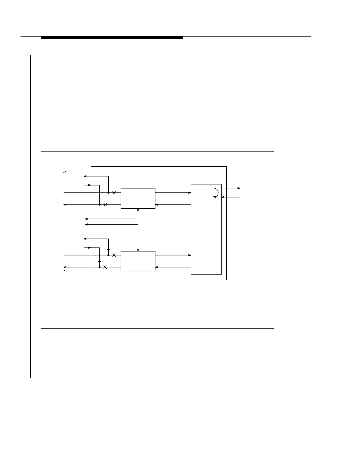
Figure 7-23. HDSL Circuit Pack Block Diagram
The distance limitations for HDSL are based on a maximum signal attenuation of
35 dB. Since signal attenuation decreases as the cable gauge (number)
decreases, the lower the gauge the greater the length the HDSL can be extended.
Table 7-7 identifies and lists these distances, as well as indicates the loss on the
line, in dB per feet, at 196 kHz.
tpa 852355/01
To/From
Lightning
Protection
Shelf
To/From
Prot. Sw.
Bus
HDSL #1
Faceplate
Mounted
Mgt. Port
HDSL to DS1
Processor &
PM Processor
DS1
Clock & Data
VT-G
Loopback
VT 1.5
Processor &
Byte
Interleave &
(Disinterleave)
VT-G
To/From
MXRVO CPs
(Service and
Protection)
To/From
Prot. Sw.
Bus
HDSL #2
HDSL to DS1
Processor &
PM Processor
DS1
Clock & Data