363-206-305
Administration and Provisioning
Issue 3 June 2000
8-65
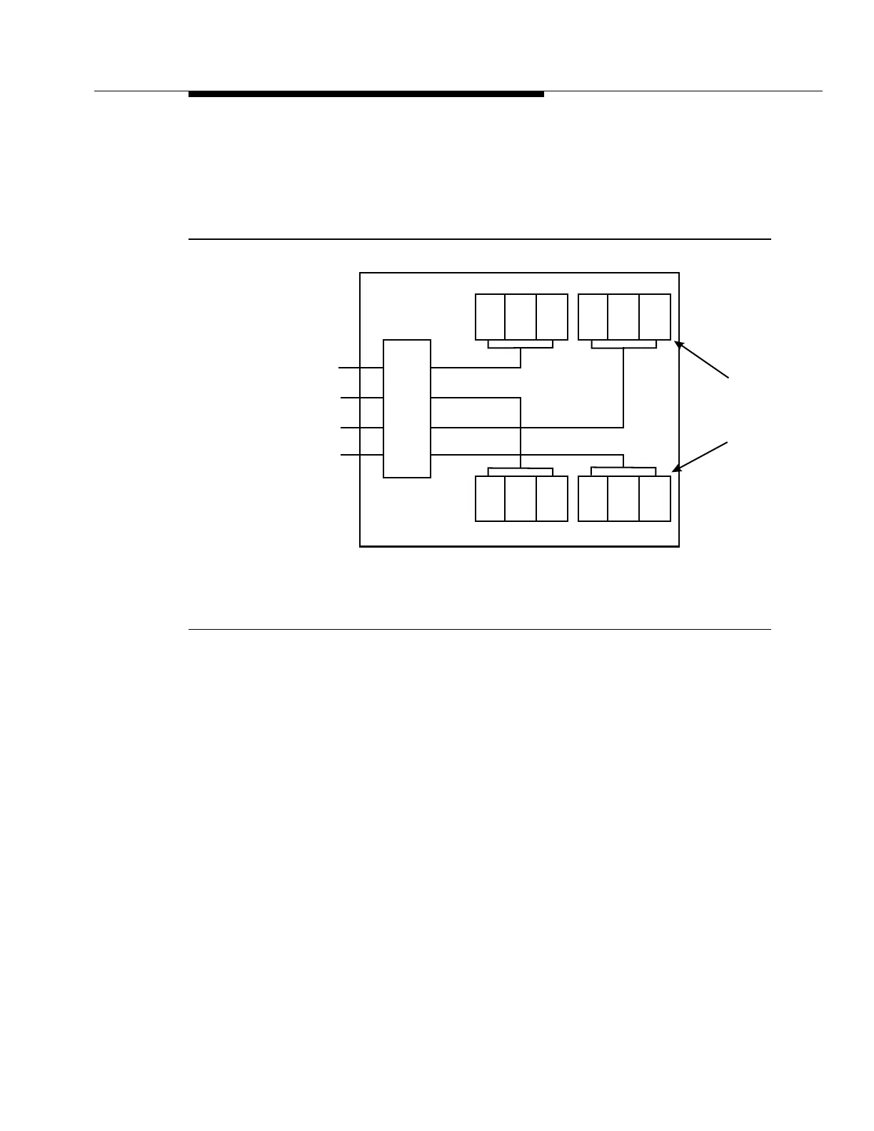
For these time slots to be correctly associated with the actual channel unit slots in
the MDS assembly, the system uses a
virtual channel unit slot
concept. You must
use the SLC-2000 host digital terminal CIT to cross-connect the real and virtual
time slots to the appropriate VRTs. Figure 8-14 shows the actual NBS
configuration with its four DSX-1 feeder signals.
Figure 8-14. Actual NBS V-DT Configuration (Octet Mode)
Using the
virtual
concept as shown in Figure 8-15, the
SLC
-2000 HDT software,
when provisioning ISDN circuits, “thinks it sees” a six-slot V-DT instead of a three-
slot V-DT. As Figure 8-15 shows, slots 4, 5, and 6 of the V-DT are
not
physically
present. However, they are present in the software and are called
virtual slots
,
actually representing the third and fourth lines on the
SPQ
494 ISDN channel
units.
When installing and cross-connecting ISDN circuits in an NBS with DSX-1 feeders
provisioned for the octet mode, you must understand the relationships between
the NBS, octet mode, and actual or virtual slots. Refer to Figure 8-15 to
understand these concepts.
■
Addressing the NBS Quadrant
. You must address each quadrant of the
octet NBS using its DT Servers address in the MDS assembly at the
SLC
-
2000 HDT (MDS shelf number, MDS shelf slot number).
D
S
X
B
I
U
DSX-1 signals
from
-2000
HDT
SLC
®
A
B
C
D
Channel
unit
slots
NBS
123 4
5
6
7
8 9 10 11 12
100046-4 12/97